


Designing a Multi-Socket IoT Energy Monitoring and Control System
 View
Expanding from a single-socket prototype to a multi-socket IoT energy monitoring system introduces significant architectural and safety challenges. In this version, the system supports four independent AC outputs, each equipped with its own energy measurement and control channel.
This transition required redesigning both the hardware layout and firmware structure to maintain stability, isolation, and scalability.
System Architecture Overview
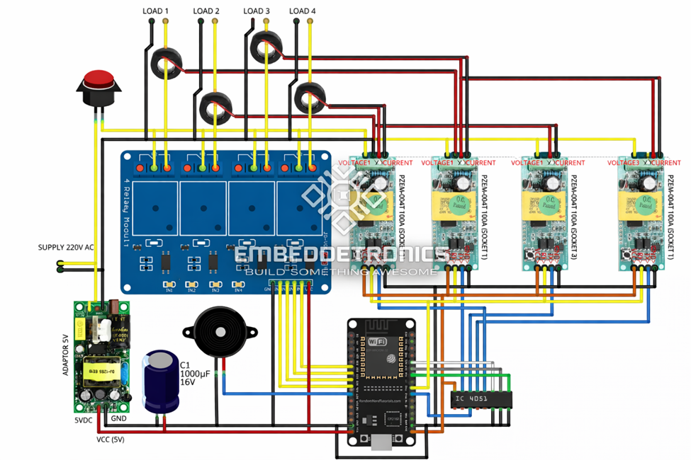
The multi-socket version integrates:
- ESP32 as central controller
- Four PZEM-004T energy modules
- 4-channel relay module
- IC 4051 multiplexer
- 220VAC to 5V switching power supply
- Firebase Realtime Database integration
The complete wiring structure is shown in the wiring diagram, where each load channel is measured independently and routed through its own relay.
Independent Channel Design
Each socket includes:
- Dedicated current transformers
- Independent voltage measurement
- Separate energy accumulation
- Individual alert threshold
The firmware stores data in structured nodes:
device1/socket1/voltage
device1/socket2/voltage
device1/socket3/voltage
device1/socket4/voltage
This ensures per-load monitoring and simplifies cloud-side analysis.
Hardware Layout and Isolation

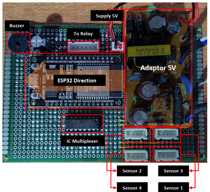
From the board layout, several critical design considerations can be observed:
- Clear separation between AC high-voltage section and low-voltage logic section
- Dedicated 5V supply module for ESP32 and relay drivers
- Use of IC multiplexer (4051) to manage multiple measurement inputs
- Relay driver isolation to protect GPIO pins
When multiple relays operate simultaneously, switching noise increases significantly. To mitigate this:
- Decoupling capacitors are placed near ESP32 supply lines
- Proper grounding strategy is implemented
- Relay flyback protection is included
These measures prevent ADC instability and WiFi communication drops.
Panel and Mechanical Design

The enclosure layout demonstrates practical installation considerations:
- Four front-access sockets
- Dedicated AC input connector
- Master ON/OFF switch
- Internal spacing for airflow
Thermal management becomes important when multiple loads operate simultaneously. Proper cable routing and spacing reduce overheating risk.
Firmware Scaling Strategy
The firmware was redesigned using channel abstraction rather than duplicating logic.
Instead of writing separate code blocks per socket, a structured array approach is used:
- Measurement array per channel
- Alert threshold per channel
- Relay status per channel
Sampling is performed sequentially to avoid communication congestion.
This approach improves maintainability and enables future expansion beyond four sockets.
Cloud Synchronization Model
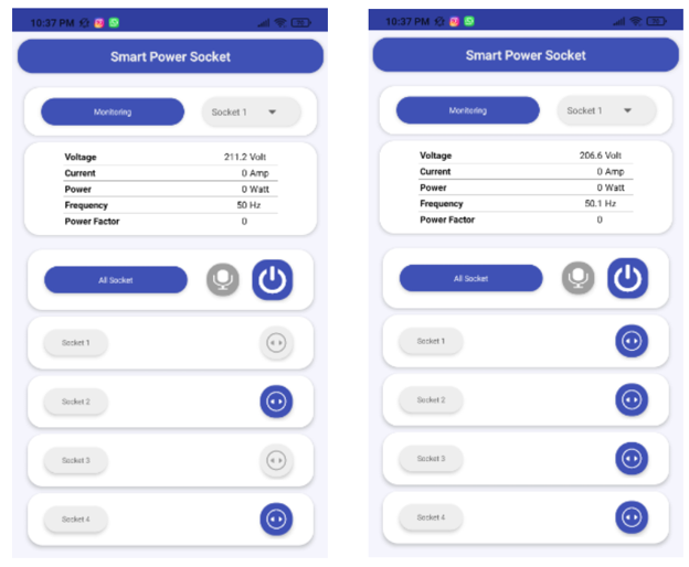
Firebase integration allows each socket to publish:
- Voltage
- Current
- Power
- Energy
- Cost
- Alert flag
The Android interface displays real-time data per socket.
This architecture supports:
- Per-load monitoring
- Independent billing estimation
- Remote supervision
- Scalable IoT deployment
Design Lessons
Moving to multi-channel AC monitoring significantly increases complexity in:
- Electrical safety
- Signal integrity
- EMI handling
- Thermal management
- Firmware modularity
A scalable IoT energy system must be designed with isolation, noise control, and structured data handling from the beginning.
This multi-socket implementation represents the evolution from a simple monitoring prototype into a structured smart power management platform suitable for laboratory, workshop, or small industrial applications.
#power meter#
#internetofthings# #Embedded#
 #powermeter#
#internetofthings#
#Embedded#
Sign In Or Register Comment after
No comments yet. Be the first to comment!