


Mastering Differential Pair Routing: Keeping Impedance Consistent
 View
View
Differential pairs form the basis for high-speed interfaces such as USB, Ethernet, and LVDS. To achieve this, we need to have consistent impedance and close proximity between both signals to ensure that the two signals arrive clean and at the same time.
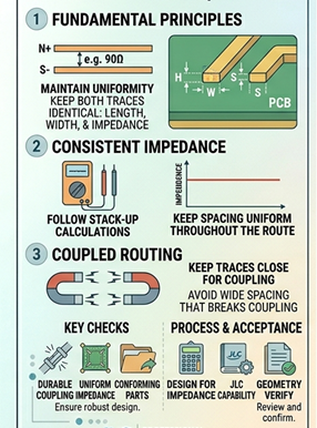
A differential pair consists of two traces, with both traces carrying opposite and equal signals from each end of the differential pair. The distance between the two traces and their geometry determine their differential impedance (typically 90 ohm or 100 ohm). Most importantly, both traces must be identical in length, width, and environment; any variation will introduce skew and degrade the quality of the signal.
Spacing between the two traces is essential. If the traces are spaced too far apart, the differential pair will lose coupling and behave as two separate traces. If the traces are spaced too closely together, the impedance will decrease. Make sure to follow any stack-up calculations you create, and keep the spacing uniform throughout the entire route of the circuit (this is especially important through bends and layer transitions).
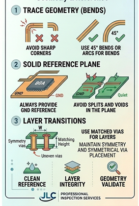
Speaking of bends, you should avoid using sharp corners when bending the traces; you should use either 45-degree bends or arcs when bending the traces to maintain a consistent impedance reading. You should also keep both traces together at all times; if you need to separate them or pass one trace through a detour, you will create a distortion in the signal that will also create an increase in EMI and noise.
You should always have a solid reference plane (usually GND) underneath the differential pair. Any disruption to the reference plane (e.g., splits and voids) causes the return current to take longer paths; therefore, an increase in EMI and noise will occur. When you change layers, always use a matched via for both traces and maintain the symmetry of the traces.
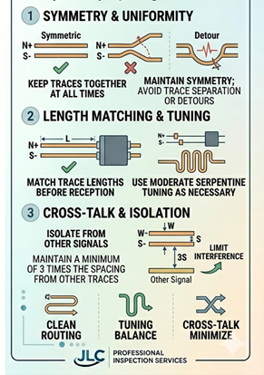
While it's important to match length, don't get carried away with it. There are some minor differences before the two lines meet that usually won’t cause a timing problem depending on the type of interface. I would use moderate serpentine tuning as necessary.
Finally, to limit cross-talk interference, keep your differential pairs away from other signals. An easy way to do this is to maintain a minimum of 3 times the spacing (in width) of the traces to other traces.
What's the bottom line? Differential routing is not just about drawing two traces. It is about maintaining symmetry, uniformity, and the electrical character of the path as a whole.
#PCB#
 #PCB#
#PCB#
Sign In Or Register Comment after
No comments yet. Be the first to comment!