


Inertial Measurement Unit (IMU) in Flight Controller Application (Part 1)
 View
View
What Is an Inertial Measurement Unit (IMU)?
An Inertial Measurement Unit (IMU) is an electronic device that measures and reports acceleration, angular velocity, and sometimes magnetic field data. It typically consists of:
- Accelerometers – Measure linear acceleration along the X, Y, and Z axes.
- Gyroscopes – Detect angular velocity to track orientation changes.
- Magnetometers (optional) – Provide heading data by measuring Earth’s magnetic field.
By combining these sensor readings, an IMU can determine an object’s movement and positioning, making it essential for applications requiring precise motion tracking.
Application in Flight Controller
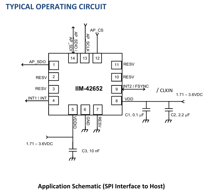
This is a typical implementation of an IMU within a Flight Controller using EasyEDA. For supporting circuits like decoupling capacitors, you should refer to the "Typical Application" section in the IMU datasheet. In this example, I am using the IIM-42652, an industrial-grade IMU designed for high-performance flight controllers. You can access the datasheet here:
IIM-42652 Datasheet(PDF) - TDK Electronics.
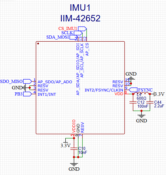
Most commonly, IMUs in this field use SPI communication instead of I2C due to its superior speed. While SPI requires more pins specifically CS (Chip Select), SDO/MISO, SDA/MOSI, and SCLK the performance trade-off is worth it.
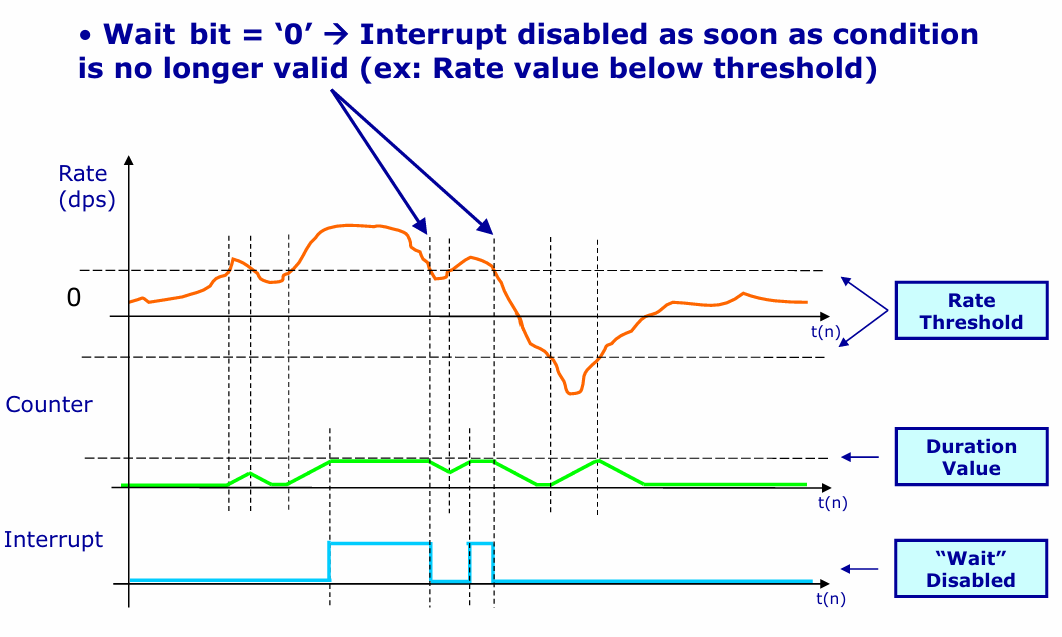
Most commmonly IMU are using SPI communication instead of I2C or others. this probably needs more Pins, such as CS, SDO/MISO, SDA/MOSI, SCLK. Maybe you asking for INT and FSYNC why they still connected into a netlabel (which is conneted into MCU). The reason is depend on the IMU that you using for. INT (interrupt) is a digital output pin from the IMU that signals the microcontroller when a specific event occurs, so the MCU doesn't have to constantly poll the IMU, saves CPU time and power by avoiding continuous polling, and the MCU can sleep until the IMU signals new data. You can use this pin when your MCU (especially STM32) still have pins that not used, but if not you can float this pin or connected this pin into the ground (check the datasheet for the best termination), but using it is highly recommended for efficiency.
FSYNC (Frame Synchronization) is a hardware pin and feature used to synchronize sensor data sampling with an external event or device. Basicly it Aligns IMU data samples with an external timing reference (e.g., a camera frame, GPS pulse, or another sensor). But you should be looked at Hwdef.dat to see is the IMU compatible with the Ardupilot environment or not.
Maybe you asked for why I added Ferrite Bead 600 Ohm in Power Rail input for IMU, which is not enter in the datasheet (see the figure in bottom).
The reason is for filtering the circuit from noise suppression. A ferrite bead is not an ideal inductor, its main purpose is not to“reflect noise and block it.”So It works by dissipating high-frequency energy as loss (heat), that is why ringing is reduced and the waveform settles faster. But because of the oscillation, you should know which the frequency that you used in the circuit (is it High or Low Frequency) and find the Capacitor for the Pi-Filter. This is the Figure that shown Pi Filter used a ferrite bead and two 100nF Capacitor.
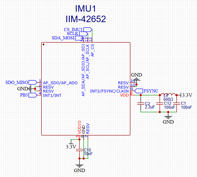
Maybe we can discuss how the Pi Filter work and how to choose the value, connected and layouting them. If youre interested you can watch this video from Robert Ferenac and explained by Eric Bogantin https://youtu.be/HaLMjVkKYMw?si=AxCk40LLvW4WpBE9. But the conclution is, the ferrite bead is important to block the noise thatr can be caused an error data IMU which is can be caused a weird moving into your UAV later.
Sign In Or Register Comment after
No comments yet. Be the first to comment!