


Introduction to Barometer for Flight Controller (Part 1)
 View
View
Welcome back to the workbench! If the IMU is the "inner ear" of your drone that handles balance, the Barometer is its sense of altitude. For anyone designing a Flight Controller (FC) from scratch, getting the barometer right is the difference between a drone that holds its height perfectly and one that randomly shoots into the sky or crashes into the ground.
Today, I am going to walk you through everything you need to know about integrating a barometer into your FC, specifically focusing on the Bosch BMP388. I have tried many sensors over the years, and this is currently one of my top recommendations for modern drone builds.
What Does a Barometer Actually Do?
At its core, a barometer measures atmospheric pressure. As your drone flies higher, the air gets thinner, and the pressure drops. The flight controller reads this tiny drop in pressure and calculates how high the drone is off the ground.
Older drones relied heavily on GPS for altitude, but GPS altitude is notoriously inaccurate (it can drift by meters!). A good barometer like the BMP388 gives you centimeter-level precision. When you switch your drone into "Altitude Hold" or "Loiter" mode, the firmware relies on this sensor to keep the drone perfectly level in the air.
Introducing BMP388
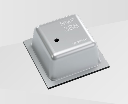
Reference: BMP388 data sheet
If you are upgrading from older chips like the BMP280 or MS5611, the BMP388 is a massive leap forward. Here is why I highly recommend using it in your next design:
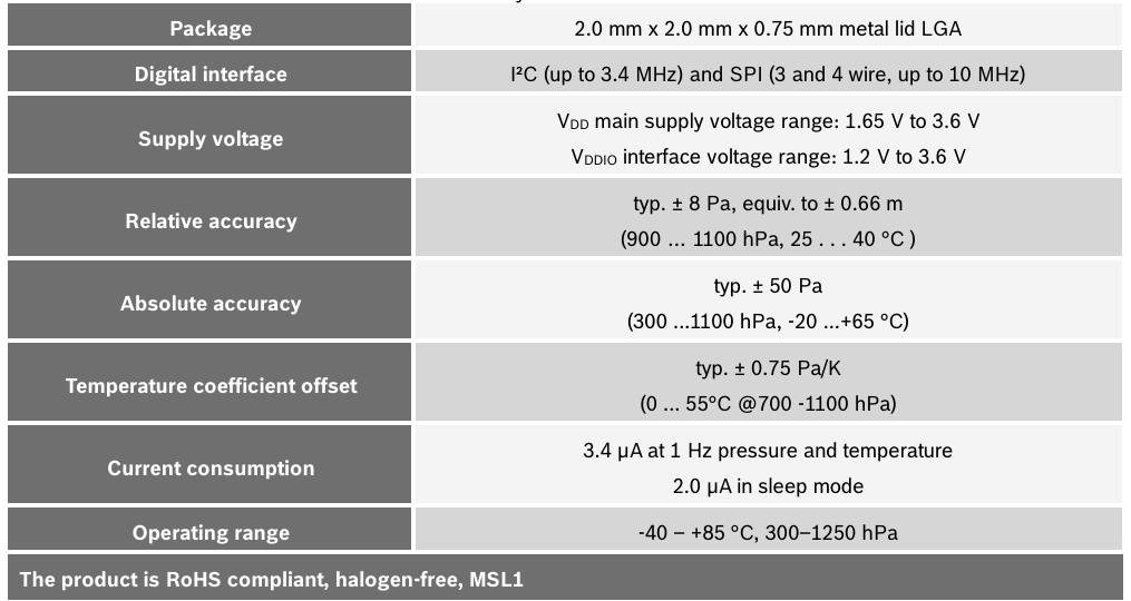
- Incredible Accuracy: It has a relative accuracy of 8 Pascals, which translates to an altitude variance of just 0.66 meters. In practice, with good filtering, it feels locked in.
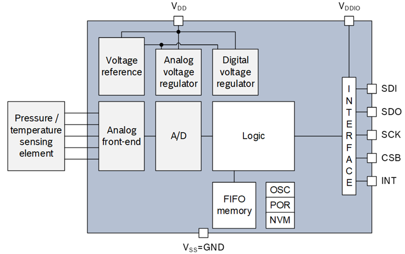
- Built-in IIR Filter: It has an Infinite Impulse Response (IIR) filter built right into the silicon. This means it can smooth out sudden spikes in pressure before the data even reaches your MCU.
- Low Power & Small Footprint: It comes in a tiny 10-pin LGA package, saving precious PCB space.
Communication
The BMP388 supports both SPI and I2C. However, for a flight controller, I strongly recommend using SPI.
You can read in embedded systems journals (like the IEEE transactions on Embedded Computing) that the I2C bus is prone to "locking up" in high-noise environments. If your I2C bus locks up mid-flight, the drone loses its altitude awareness and might drop out of the sky. SPI does not have this vulnerability because it uses dedicated push-pull lines without the need for pull-up resistors.
- CSB Pin: Connect this to your MCU for Chip Select.
- SDI/SDO/SCK: These are your standard SPI data and clock lines.
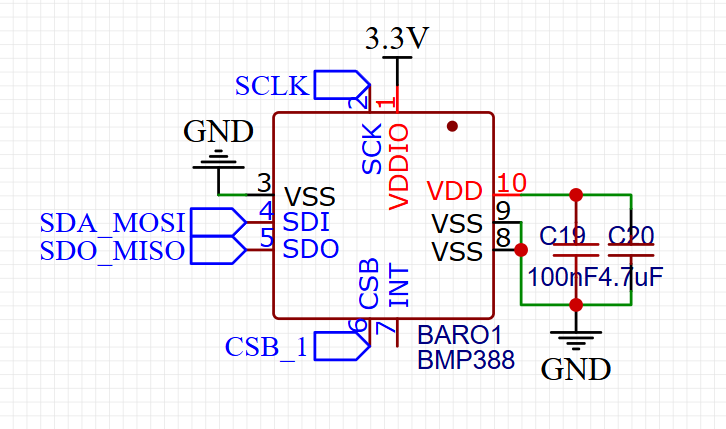
I have utilized the high-speed 4-wire SPI configuration for the BARO1 (BMP388). You can clearly identify the interface signals: Serial Clock SCK is routed to pin 2 and tied to the SCLK net; Serial Data Input SDI, serving as the MOSI line, is handled by pin 4 via the SDA_MOSI net; and Serial Data Output SDO, acting as the MISO line, originates from pin 5 on the SDO_MISO net. To manage bus activation, Chip Select CSB, which is an active-low signal, utilizes pin 6 and connects to the CSB_1 net label. By defining this specific CSB_1 net within your firmware, you instruct the MCU to pull this line to 0V only when it intends to communicate with this specific barometer.
I have tried minimal decoupling configurations in the past, and I have always found them to be highly problematic, leading to unstable altitude readings. Therefore, in this configuration, I have utilized bulk and bypass decoupling capacitors in parallel on Pin 10 (VDD). Specifically, I have implemented C19, which is a 100nF ceramic capacitor for high-frequency noise suppression, and C20, a larger 4.7uF bulk capacitor to stabilize lower-frequency voltage dips, both referenced to GND. This dual-capacitor approach is essential to maintain a rock-steady reference voltage for the internal ADC during conversion cycles.
Finally, you can see from the wiring that I recommend tying all available VSS (Ground) pins (pins 3, 8, and 9) directly to the digital ground plane (GND). This technique reduces the chip's internal ground loop impedance and minimizes digital switching noise from affecting sensitive analog pressure measurements. Note that pin 7 (INT) is correctly left floating (No Connect), which aligns with my recommendation to simplify the sensor interfacing for the main flight controller processor.
Sign In Or Register Comment after
No comments yet. Be the first to comment!