


Compass in Flight Controller? Is it Necessary?
 View
View
Building your own Flight Controller (FC) is a major milestone for any drone engineer. While gyroscopes and accelerometers (the IMU) provide stability, a magnetometer often called a digital compass to provides the "sense of direction" necessary for autonomous flight.
Here is a guide on why and how to integrate the LIS3MDL magnetometer into your custom flight controller project.
Why Do You Need a Compass in a Flight Controller?
A gyroscope can calculate orientation, but it suffers from drift over time. Without a reference point, the drone's heading (Yaw) will slowly rotate in the software even if the drone is pointing straight.
- Heading Accuracy: The magnetometer uses the Earth's magnetic field to provide an absolute North reference.
- Autonomous Navigation: For features like "Return to Launch" (RTL), Position Hold, or Waypoint missions, the FC must know exactly which way it is facing to move toward a coordinate.
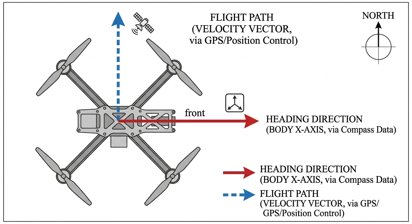
- GPS Limitation: A GPS can tell you where you are and your ground speed, but it cannot tell you which way the drone is "nose-in" while hovering.
This image illustrates that a drone can move forward while facing sideways; the compass tells the FC the "facing" direction.
The Challenge: Magnetic Interference
The biggest mistake in FC design is placing the magnetometer "on-board" near high-current components.
-
High-Current Wiring Effects: According to the LIS3MDL datasheet, high current in wiring and printed circuit traces can cause significant errors in magnetic field measurements.
-
The 10mA Rule: Conductor-generated magnetic fields add to the Earth’s field. You must keep currents higher than 10 mA at least a few millimeters away from the sensor.
-
EMI Sources: Motors, ESCs, and battery leads create massive electromagnetic interference (EMI).
Design Pro-Tip: Follow the "Cube Orange" or "Pixhawk" architecture. They often use a multi-PCB stack where the sensitive sensors (like the LIS3MDL) are separated from the power distribution and noisy IoT/Microcontroller logic.
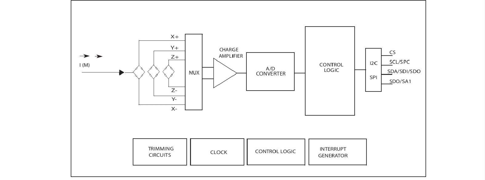
LIS3MDL Magnetometer

The LIS3MDL is an ultra-low-power, high-performance 3-axis magnetometer. It is ideal for custom FCs due to its flexibility.
Key Specifications:
-
Selectable Full Scales: ±4/±8/±12/±16 gauss.
-
Digital Interfaces: Supports both I2C (standard and fast mode) and SPI interfaces.
-
Operating Voltage: 1.9 V to 3.6 V.
-
Resolution: 16-bit data output.
Hardware Installation & Schematic Guide
To integrate the LIS3MDL into your flight controller, follow the standard I2C implementation as shown in my provided schematic.
Wiring the LIS3MDL (I2C Mode)
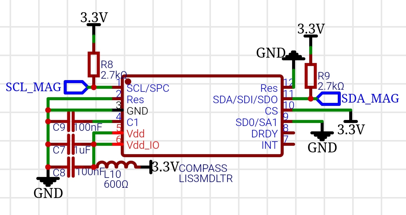
To enable I2C mode, the CS (Chip Select) line must be tied high to Vdd_IO.
| Pin # | Name | Function | Connection |
|---|---|---|---|
| 1 | SCL/SPC | I2C Clock | To MCU SCL |
| 11 | SDA/SDI/SDO | I2C Data | To MCU SDA |
| 10 | CS | Mode Select | Tie to 3.3V (Logic High) |
| 9 | SDO/SA1 | Address Select | Tie to GND or 3.3V |
| Critical External Components |
- Decoupling Capacitors: You must connect a 100nF capacitor (C1) between pin 4 and GND. Additionally, the Vdd line requires a 100nF high-frequency ceramic capacitor and a 1uF low-frequency electrolytic capacitor.
- Pull-up Resistors: Both SCL and SDA lines must be connected to Vdd_IO through external pull-up resistors (typically 2.2kOhm to 10kOhm. My schematic uses 2.7kOhm (R8, R9), which is excellent for Fast Mode I2C.
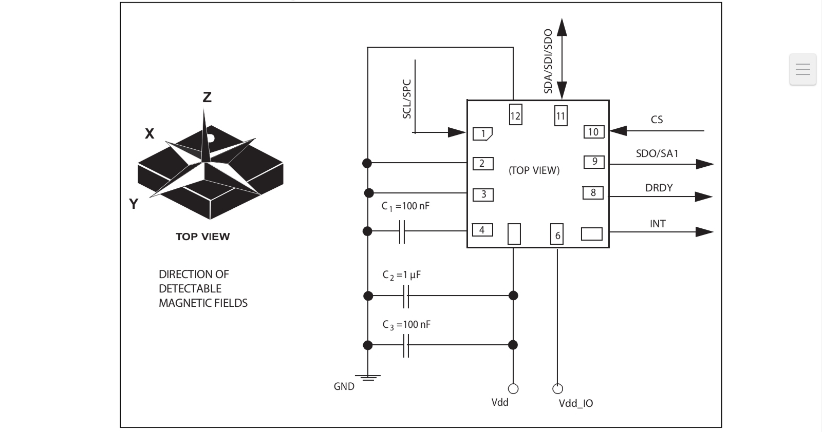
This diagram in the datasheet provides the "golden standard" for your PCB layout.
Using an External Compass (GPS Combo)

If your on-board PCB layout is too cramped or noisy, the standard industry practice is to use an External Compass.
Most modern drone GPS modules (like those based on the u-blox M8N or M10) include an internal magnetometer.
- The Technique: You bypass the on-board LIS3MDL and connect the I2C wires (SCL/SDA) from the GPS module to your FC's I2C port.
- Placement: The GPS/Compass is then mounted on a "GPS Mast" high above the motors and battery.
- Software Configuration: In firmware like ArduPilot or PX4, you simply select the "External" compass as the primary (Compass 1) and disable the "Internal" one to avoid interference.
Resources
- Official Datasheet: STMicroelectronics LIS3MDL Product Page.
- Journal/Documentation: Refer to the ArduPilot Compass Calibration Guide for details on how to handle "Soft Iron" and "Hard Iron" offsets in your custom code.
- PCB Design Jurnal: Search for "Minimizing magnetic interference in small UAVs" on IEEE Xplore for academic papers on trace routing for magnetometers.
Sign In Or Register Comment after
No comments yet. Be the first to comment!