


The AMS1117, is it Good Enough for Your Flight Controller?
 View
View
In my journey building flight controllers, I have seen many designers default to the AMS1117. While it is a "workhorse" for basic digital projects, using it to power a precision flight controller is like putting a noisy lawnmower engine into a luxury car.

If you want your EKF to be stable and your sensor to be accurate, you need a "Silent" power rail. Here is how I explain the shift from basic regulation to professional power integrity.
The AMS1117 Problem: Why it is "Dirty"

The AMS1117 is a linear regulator, but it is not a "Low-Noise" regulator. For a drone engineer, it has three major flaws:
- High Dropout Voltage: It usually requires about 1.1V to 1.3V of "headroom." If your battery drops, your 5V rail might dip, causing your 3.3V sensor rail to brown out.
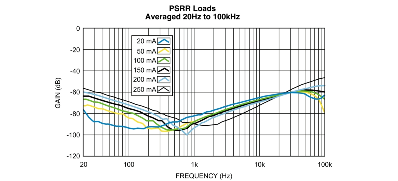
- Poor PSRR: Power Supply Rejection Ratio (PSRR) measures how well the LDO blocks noise from the input (like ESC switching noise). The AMS1117 has a low PSRR at high frequencies where motors operate.
- High Output Noise: It generates its own internal electrical "hiss" which can confuse the sensitive ADCs in your IMU.
Ultra-Low Noise LDOs
When I design a professional FC, I look for LDOs specifically marketed as Ultra-Low Noise or High PSRR. Examples the LP5907 or MIC5219.
You should look for:
- PSRR (dB): Look for values above 60dB or 70dB at 10kHz. This tells you the LDO is an active filter against motor noise.
- Noise (uVRMS): A silent LDO should have an output noise below 10uVRMS (from 10Hz to 100kHz).
- Accuracy: Look for 1% or 2% output voltage accuracy to ensure your sensors always see exactly 3.3V.
This images shown the PSRR vs. Frequency graph in an LDO datasheet. This curve illustrates how effectively the regulator blocks noise at different motor RPM frequencies.
Designing the "Silent" Rail Architecture
An LDO alone is not enough. You must build a Pi-Filter (C-L-C) to protect your sensors.

Here is the standard implementation I use for the 3.3V rail. The Component Recipe:
- Input Bulk Capacitor:22uF tantalum or high-quality ceramic. This handles the "big" ripples from the main battery.
- The Ferrite Bead: Use a 10uH or 600Ohm (at 100MHz) ferrite bead between the LDO and the sensor. This acts as a wall against high-frequency RF noise.
- Output Decoupling: Use a combination of 10uF (for stability) and 100nF (for high-frequency spikes).
Layout
In my experience, the schematic is only 50% of the work. The other 50% is the PCB Layout.
- Ground Planes: Use a solid Ground Plane. Do not "snake" your ground traces.
- Kelvin Sensing: Place your output capacitors as close as humanly possible to the Vdd pins of your IMU and Compass.
- Isolation: Keep the noisy AMS1117 (if used for LEDs or non-critical parts) on a completely different side of the board from your sensor LDO.
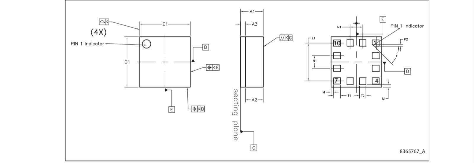
VFLGA-12 package outline and pin indicators to assist in correct PCB footprint design.
Recommended Resources
Professional Websites
- TI Precision Hub: An incredible resource for learning about LDO noise. Texas Instruments - LDO Noise Demystified
- Analog Devices (ADI) Education: Deep dives into PSRR and power integrity. Analog Devices - Power Management Design
Journals and Papers
- "Power Supply Noise Reduction in Sensor Systems": Search this on** IEEE Xplore**. It explains why high-frequency noise causes "bias instability" in gyroscopes.
- "System-on-Chip (SoC) Power Integrity": While advanced, this journal content explains the importance of decoupling capacitors like the 22uF and 100nF combo I mentioned.
Sign In Or Register Comment after
No comments yet. Be the first to comment!