


 View
View
Why CAN? (The Differential Advantage)
In many DIY builds, I2C is the default because it’s easy. However, I2C was designed for "chip-to-chip" communication on a single PCB, not for running wires across a drone frame. On a drone, long wires act like antennas, picking up massive electromagnetic interference (EMI) from your motors.
CAN (Controller Area Network) is different. It uses Differential Signaling. Instead of one signal wire, it uses two: CAN High (CANH) and CAN Low (CANL). The receiver only cares about the difference between them. If noise hits the wire, it usually hits both equally, and the difference remains the same.
CAN allows for four different message types. They are the data frame, remote frame, overload frame, and error frame. A standard CAN data frame makes use of the identifier, the data, and data length code, the cyclic redundancy check, and the acknowledgment bits. Both the RTR and IDE bits are dominant in data frames. If the recessive acknowledge bit at the receiving end is overwritten by a dominant bit, both the transmitter and receiver recognize this as a successful transmission.
A CAN remote frame looks similar to a data frame except for the fact that it does not contain any data. It is sent with the RTR bit in a recessive state; this indicates that it is a remote frame. Remote frames are used to request data from a node. When a node detects an error in a message on the CAN bus, it transmits an error frame. This results in all other nodes sending an error frame. Following this, the node where the error occurred retransmits the message. The overload frame works similarly but is used when a node is receiving frames faster than it can process them. This frame provides a time buffer so the node can catch up.
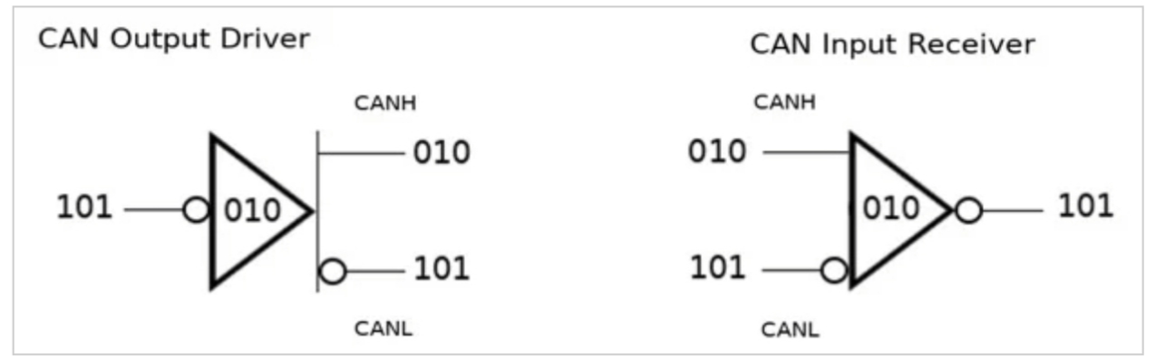
That figure shows a simplified version of a CAN transceiver's output and input. The '101' bitstream is coming from/going to a CAN controller and/or microcontroller. Notice that when the controller sends a stream of bits, these are complemented and placed on the CANH line. The CANL line is always the complement of CANH. For arbitration to work, a CAN device must monitor both what it is sending and what is currently on the bus, i.e., what it's receiving.
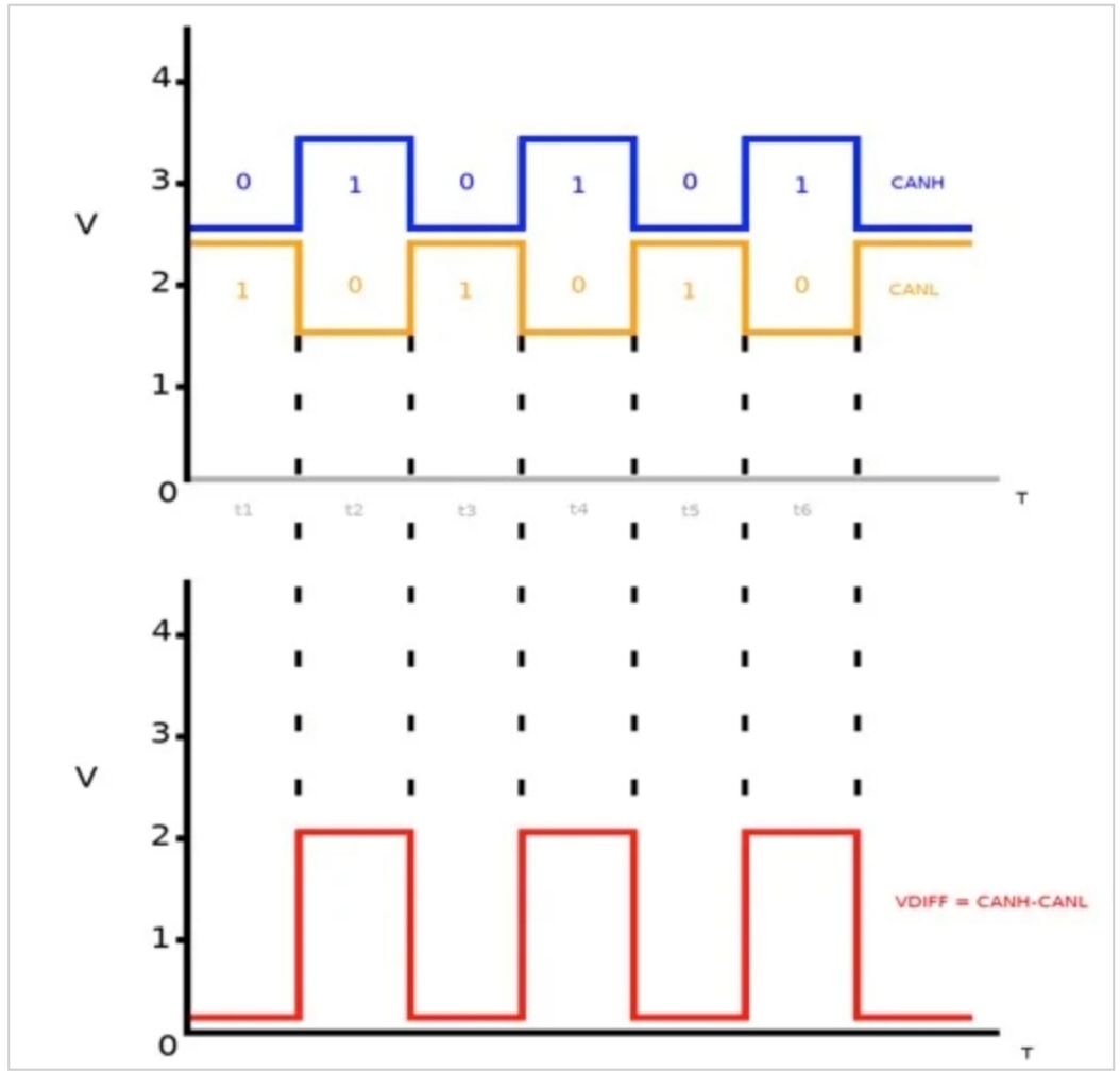
The figureshows both the CANH and CANL signals simultaneously so that you can see the CAN bus in action. Plotted below the bus signals is the differential voltage that corresponds to the dominant and recessive states of the CAN signals. The first three segments in time, t1–t3, are drawn to match up with the three bits shown above in Figure 5. We will look at this from the perspective of the output driver. The driver's input initially sees a '1' and complements this to a zero, which is placed on CANH. CANL sees the complement of CANH and goes high. This is shown as t1 in Figure 6. Notice that the CANH and CANL voltages are offset from one another. During time t1, CANH – CANL is very close to zero, since CANH and CANL are almost the same voltage. This period, where the driver is sending a logic '1' resulting in CANH and CANL being close to the same voltage, is what we call the CAN recessive state.
The next bit sent is a '0'. CANH gets its complement and CANL again gets the complement of CANH. Notice this time that the CANH and CANL voltages are not close to one another. Therefore, the differential voltage (VDIFF) is larger. This is the CAN dominant state. We say that the logic is inverted because a '1' takes the bus low and a '0' brings it high. The input receiver works in a similar fashion.
You can see the visual explanation of this noise rejection on the All About Circuits website in their Introduction to CAN Bus https://www.allaboutcircuits.com/technical-articles/introduction-to-can-controller-area-network/.
Drop a comment if you have ever had a "frozen" I2C bus mid-flight. it’s usually because of the noise.
The Hardware: Transceivers and Termination
Looking at your schematic, I see we’ve moved beyond simple logic levels. Your STM32 can't talk to the CAN bus directly; it needs a "translator" called a Transceiver.
The SN65HVD230 Transceiver
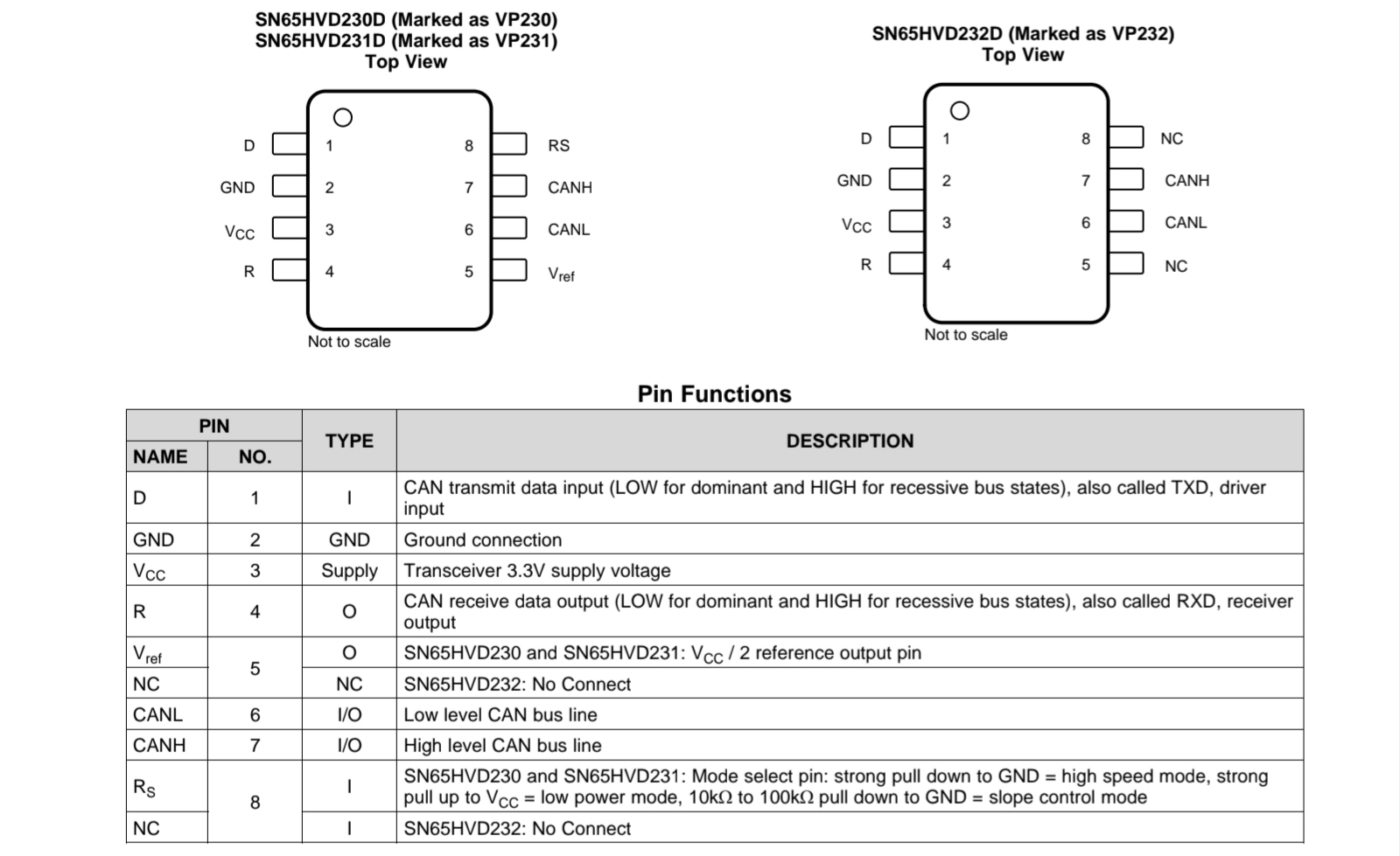
This chip converts the 3.3V digital signals from your MCU into the differential voltages required for the bus.
- Check the Datasheet: You should download the SN65HVD230 datasheet from Texas Instruments.
This diagram illustrates the typical application circuit from Reddit https://www.reddit.com/r/PrintedCircuitBoard/comments/jcgqch/sn65hvd230_can_transceiver_breakout/?rdt=61456
The 120Ohm Termination Rule
High-speed signals on a bus can "reflect" back when they hit the end of the wire, like a wave hitting a wall. This causes data corruption.
- The Fix: You MUST place a 120Ohm (2 x 60Ohm) resistor at the two physical ends of your bus.
- In your FC: I noticed your design includes a termination header. This is perfect.
Sign In Or Register Comment after
No comments yet. Be the first to comment!