


 View
View
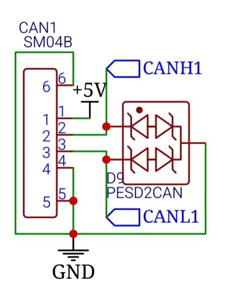
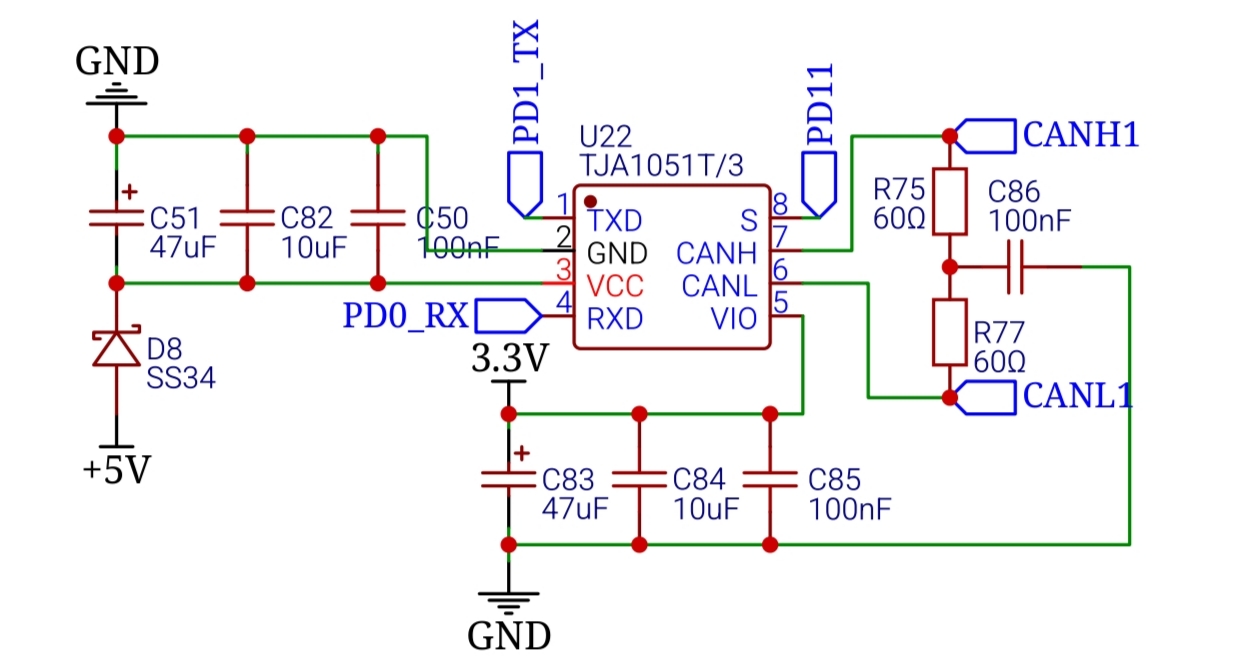
This is my schematic version, using TJA1051T
For a deep dive into why this resistance matters, check out this video on YouTube: https://youtu.be/fVy_EXkMKMg
DroneCAN: The Software Layer
Hardware is only half the battle. To make everything talk nicely, we use DroneCAN (formerly UAVCAN). It is an open-source, decentralized protocol that allows your FC to manage multiple nodes without the CPU overhead of a master-slave relationship.
- Official Website: Visit https://dronecan.github.io/?hl=id-ID to see the full specification.
- ArduPilot Integration: ArduPilot has a comprehensive https://ardupilot.org/copter/docs/common-uavcan-setup-advanced.html?hl=id-ID that explains how to configure your parameters to recognize CAN-based GPS and Compass modules.
Drop a comment if you want to see the specific C++ code I use to initialize the CAN peripheral on an STM32. it's a bit more involved than a standard UART setup!
Practical Implementation Tips
- Twisted Pairs: You should always twist your CANH and CANL wires together. This ensures that any noise that hits the wire hits both lines identically. I recommend at least 30 twists per meter.
- Cable Routing: Never run CAN wires perfectly parallel to your high-current battery leads. Cross them at 90-degree angles if you must.
Help Me Help You: The Layout File
To give you a truly high-quality review of your EMI performance, I need you to export your PCB Layout file (the .json or Gerber files from EasyEDA) and send it to me. While the schematic looks great, the Layout is where the "Silent Power Rails" and "CAN Integrity" live or die. If I can see your trace routing, I can give you a "Pro" checklist on:
- Ground plane separation for the LIS3MDL.
- Differential pair routing for your CAN lines.
- Placement of your 22uF and 10kOhm components relative to high-speed lines.
Are you planning to run your LIS3MDL compass via the on-board I2C, or are you moving it to an external CAN node to get it further away from the motor interference?
Sign In Or Register Comment after
No comments yet. Be the first to comment!