


Implementing FRAM in Flight Controller Architecture
 View
View
When we design custom hardware for Drone Racing or complex autonomous missions, we often focus heavily on the MCU processing power and the gyro update rates. However, there is a silent workhorse on the board that dictates how fast and reliably we can save critical flight data: the non-volatile memory.
Today, we are going to explore why traditional EEPROM is becoming a bottleneck and how implementing FRAM (Ferroelectric RAM) in my Flight Controller schematic ensures lightning-fast, bulletproof data storage.
The Bottleneck: Why Not EEPROM?
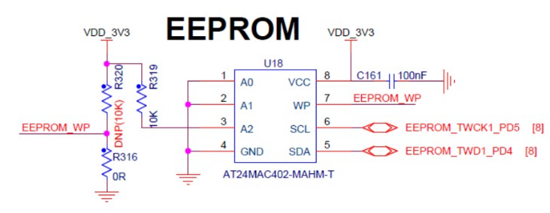
For years, flight controllers used standard EEPROM chips to save PID settings, calibration data, and waypoint missions. While EEPROM is cheap and widely available, it has a major flaw: write speed. Writing data to an EEPROM requires a physical charge pump mechanism inside the silicon, which introduces a delay of several milliseconds per write cycle.
If you are flying a high-speed drone and need to log blackbox data or save parameters on the fly, an EEPROM simply cannot keep up. Furthermore, EEPROMs typically wear out after 100,000 write cycles. In a heavily tested Flight Controller, you can hit that wear-out limit faster than you think.
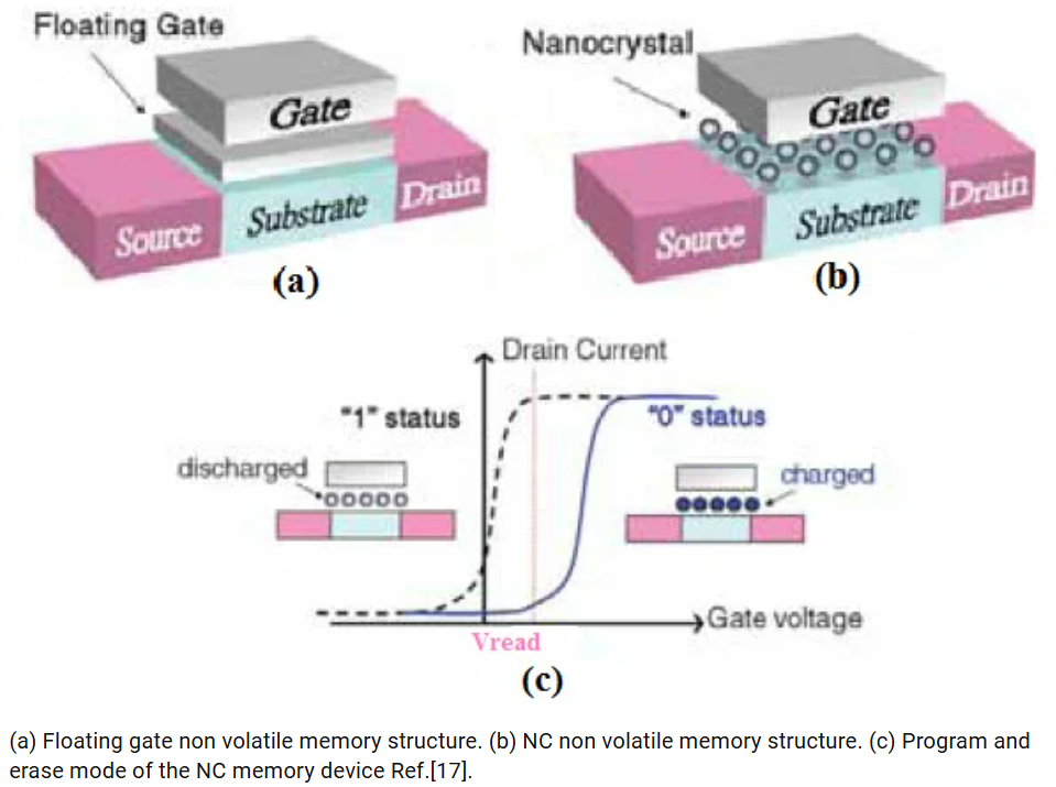
If you want to understand the deep theory of how traditional memory limitations affect embedded systems, you can check on this paper: https://www.researchgate.net/figure/a-Floating-gate-non-volatile-memory-structure-b-NC-non-volatile-memory-structure_fig2_250308372. They have great articles breaking down the physics behind flash and EEPROM wear-out.
The FRAM Advantage: FM25V02A-GTR
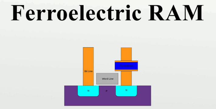
- <input disabled type="checkbox"> Enter FRAM. Unlike EEPROM, FRAM uses a ferroelectric film to store data. This means it writes data almost instantly as fast as the SPI bus can clock it in.
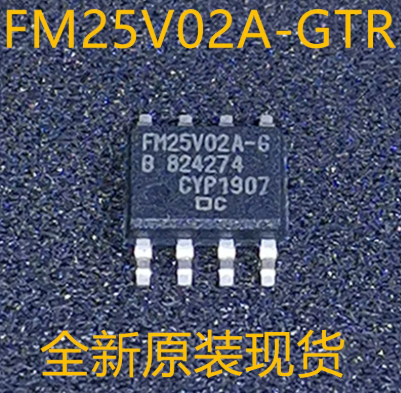
For my Flight Controller, I specifically chose the FM25V02A-GTR, a 256-Kbit F-RAM chip. According to its datasheet, this chip supports NoDelay writes and an astonishing high-endurance of 100 trillion read/write cycles. It is practically infinite for our use case. Furthermore, it operates incredibly fast, supporting SPI clock frequencies up to 34 MHz.
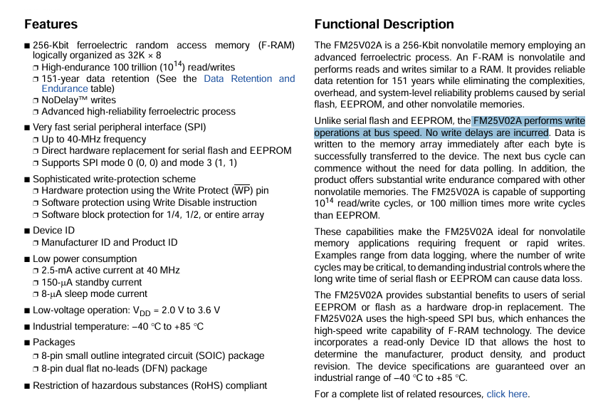
Take a look at the FM25V02A datasheet. Capture a screenshot of the "Features" section on page 1. This images shown highlights the "NoDelay Writes" and "100-Trillion Read/Write Cycles" bullet points.
Drop a comment if you want me to do a deeper dive into the physics of ferroelectric crystals and how they hold logic states without power!
Wiring the High-Speed SPI Bus
Integrating the FM25V02A into the Flight Controller is straightforward but requires clean, precise PCB routing. Because this FRAM operates at up to 34 MHz, we connect it directly to the fast SPI bus of our MCU.
This images shown the exact routing and support components required for the FM25V02A to function stably.
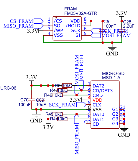
In my schematic, the FM25V02A chip is connected via the four standard SPI lines: MOSI, MISO, SCK, and M_CS_FRAM (Chip Select). However, there is a lot more going on to ensure stability:
- Clean Power: To ensure signal integrity during rapid, high-frequency read/write operations, I placed a 100nF decoupling capacitor (C20) right next to the VDD pin (pin 8) operating at 3.3V.
- State Protection: You will notice three 10kOhm resistors (R23, R24, and R25). R25 pulls the Chip Select line high to 3.3V to prevent the FRAM from accidentally activating during the MCU's boot sequence.
- Hardware Locking: I also used 10kOhm resistors to pull the WP (Write Protect) on pin 3 and HOLD on pin 7 high to 3.3V. By pulling these high, we tell the chip to always allow writes and never pause communication, ensuring the data stream from the flight controller is never bottlenecked.
Software Integration
Hardware is useless without the right software. When compiling firmware, we must define the storage chip so the MCU knows exactly how to talk to it.
In ArduPilot, FRAM is highly favored for saving parameters and waypoints because the instant write-speed prevents the main flight loop from locking up or hesitating during a write operation. You configure the hardware definitions (hwdef) to map the exact SPI bus and Chip Select pin to the internal FRAM driver.
You can check on this website for the exact ArduPilot developer documentation regarding memory mapping: ArduPilot Storage Allocation.

Sign In Or Register Comment after
No comments yet. Be the first to comment!