


Power Isolation to Securing the Main MCU with a Dedicated Servo Rail
 View
View
When designing hardware for custom drones or autonomous vehicles, we often focus on the "brain" of the system, the main Microcontroller Unit (MCU). But no matter how fast your MCU is, it will completely fail if the power supplied to it is dirty or unstable.
Today, we are going to talk about one of the most critical power design rules in drone hardware: physically separating the "thinking" from the "moving" by securing the main MCU with a Dedicated Servo Rail.
Back-EMF and Voltage Spikes
In a drone system, the flight controller must constantly command motors (via ESCs) and physical servos. These are heavy inductive loads. When a servo motor moves rapidly, abruptly stops, or reverses direction, the magnetic coils inside it act like a generator. They shoot a high-voltage surge of current back into the power line. This is known as Back-EMF (Electromotive Force).
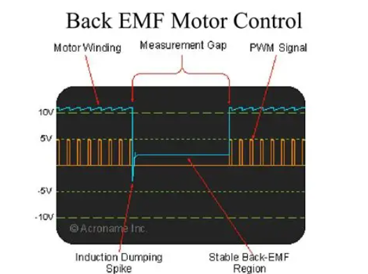
If your delicate 3.3V or 5V MCU power rail is directly connected to the same power line as your servos, these sudden voltage spikes can easily reach 8V or more. When this high-voltage transient hits the MCU, it will either instantly reset (causing a mid-air brownout) or permanently destroy the silicon.
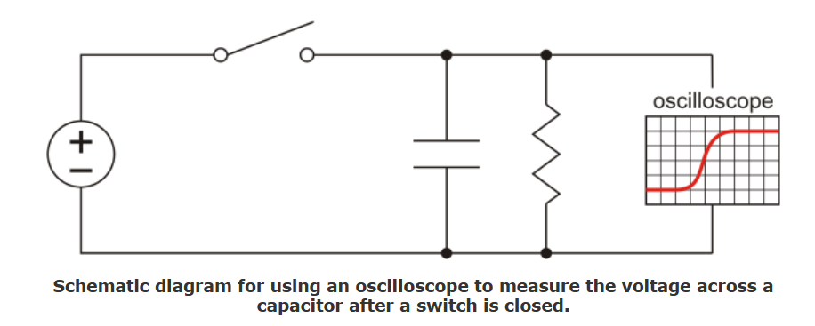
For a deep technical explanation of how motor inductance causes these destructive spikes, you can check on this website from Pololu: Understanding Destructive LC Voltage Spikes.
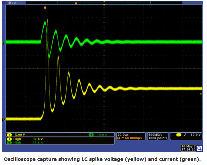
This image shown exactly how a stable 5V line can violently spike up to nearly 12V when an inductive load is connected!
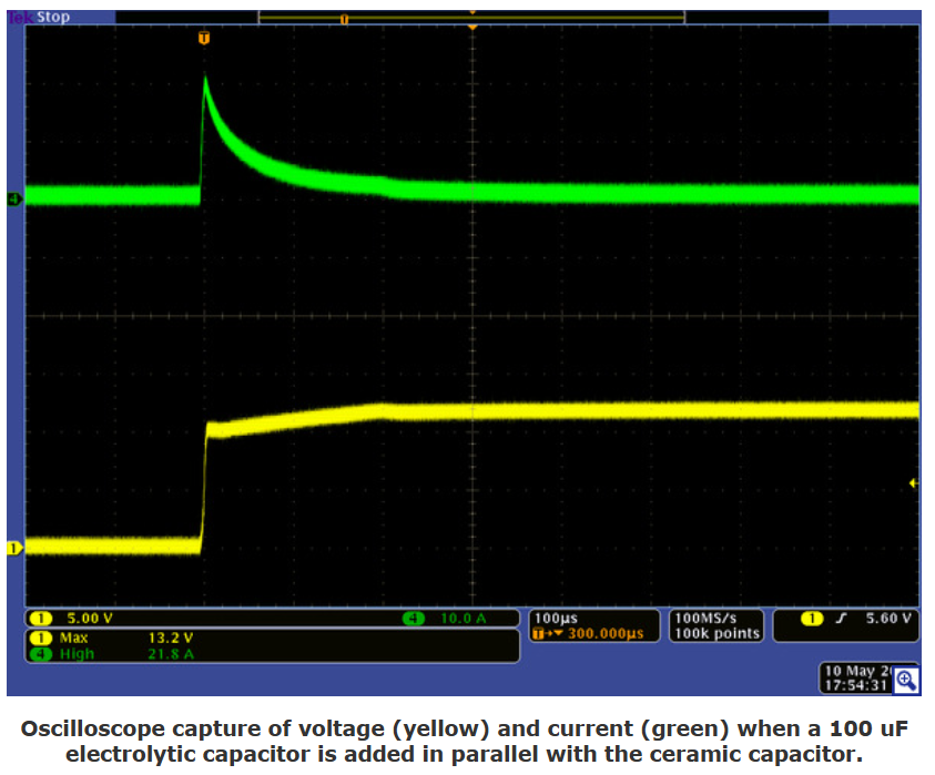
The large capacitor prevents the voltage from changing quite as quickly, yet its high ESR prevents it from drawing as much initial current. Here is the result when we added a 100 uF electrolytic capacitor in parallel with our 10 uF test capacitor:
The Schematic Solution: The Dedicated Servo Rail
To protect our Flight Controller, we use a strategy called "Power Isolation." If you look at the design of my Flight Controller, the power supply for the MCU (often labeled VCC) and the power supply for the PWM outputs (the Servo Rail) are completely separated.
They do not share a 5V source.
- The MCU Power: The brain gets its clean 5V from our heavily filtered, dual-redundant power module inputs.
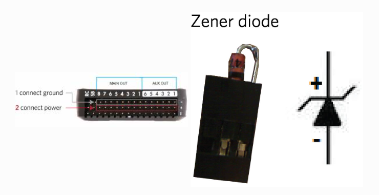
- The Servo Power: The servos get their power from an external BEC (Battery Eliminator Circuit) provided by the ESC or a standalone regulator, which plugs directly into the Servo Rail headers.
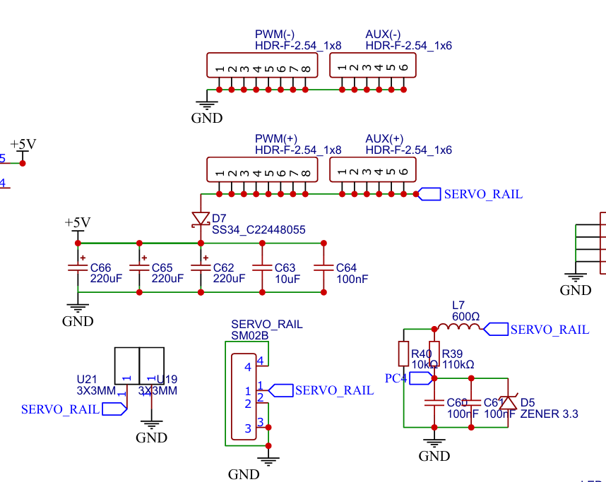
This is a cropping the "SERVO RAIL" and PWM output pin headers from my Flight Controller schematic. The 5V line on these pins is completely isolated from the MCU's 3.3V and 5V logic rails.
By completely separating the positive voltage traces on the PCB, any Back-EMF spikes generated by the servos stay trapped on the Servo Rail. The only things the MCU and the servos share are the PWM signal wires and the Ground Reference (GND).
Managing Spikes
Even though the MCU is isolated, we still don't want massive voltage spikes bouncing around our Servo Rail, as they can damage other connected peripherals.
In professional hardware design, we mitigate this by adding protection components directly to the power rails. For my Flight Controller designs, it is standard practice to place heavy filtering near the power inputs, such as a large electrolytic capacitor combined with smaller ceramic capacitors (like a 10uF and 100nF) placed close to the active components to absorb high-frequency noise.
For extreme protection, aerospace and racing drones use TVS (Transient Voltage Suppression) diodes. These diodes act like a pressure relief valve, instantly clamping any voltage spike that exceeds a safe threshold.
You can see an incredibly detailed hardware test of how these components protect your drone in this video from Chris Rosser on YouTube: Protect Yourself from ESC Voltage Spikes: Testing Capacitors and TVS Diodes. He hooks up an oscilloscope to a live drone and proves exactly why we need this hardware!

Have you ever fried a flight controller because you plugged a servo into the wrong rail? Drop a comment below and share your hardware disaster stories so we can learn from them!
ArduPilot Standards: Wiring It Safely
This hardware isolation strategy is so critical that major firmware platforms like ArduPilot strictly mandate it in their official documentation. ArduPilot software expects the hardware designer to separate these power domains.
You can check on this website for the official ArduPilot hardware wiring guidelines: Powering the Pixhawk.
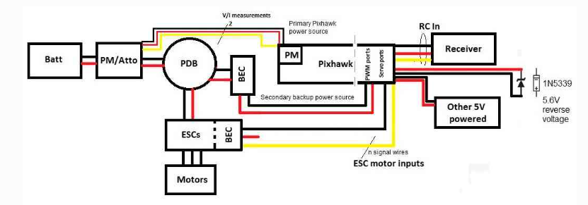
The block diagram below synthesizes an overview of Pixhawk’s power and ESC wiring. In this diagram, a 3DR power module (or equivalent device) powers Pixhawk through its power port (primary source). One power source is enough but obviously not redundant if the power module fails to power this primary source. Therefore the diagram adds a second backup power source via a 5V BEC that wires to Pixhawk’s output servo rail. If the primary source fails, Pixhawk will automatically switch to this second power source.
Sign In Or Register Comment after
No comments yet. Be the first to comment!