


Integrating Safety Switches and Relay Drivers for Custom Drone Missions
 View
View
For complex custom missions like a UAV payload dropping system integrated with LoRa or GSM tracking modules—we need physical, reliable control over external hardware. Today, I am going to show you how I integrated Safety Switches and Relay Drivers into my Flight Controller schematic using specific components like the 1N4148W diode, ensuring maximum safety and mission capability.
Part 1: The Safety Switch (Hardware Arming)
Software arming via your radio transmitter is great, but when you have a large drone carrying a heavy payload, you need a physical, hardware-level interrupt. A hardware safety switch prevents the PWM signals from reaching the motors until you physically press a button on the drone, ensuring the propellers cannot spin while you are handling the aircraft.
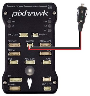
In my Flight Controller schematic, the safety switch circuit is connected via a secure JST-style SM03B connector. To ensure the physical button signal sent to the MCU is perfectly clean, I designed a hardware debouncing circuit. The signal pin is pulled up using a 10kOhm resistor (R51), and we add a 100nF capacitor (C64) in parallel to ground. This simple 100nF capacitor acts as a low-pass filter, ensuring the MCU reads a single clean press instead of a noisy, bouncing electrical signal.
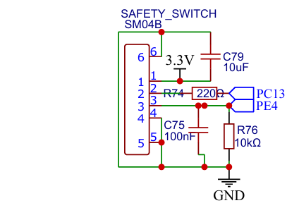
The image shown of my schematic that I just provided, that showing the SAFETY SWITCH section. This images shown exactly how the debouncing capacitor and pull-up resistor are routed to the SM03B connector
You can check on this website for the exact ArduPilot hardware implementation of this switch: ArduPilot Safety Switch Documentation.
LED Meaning
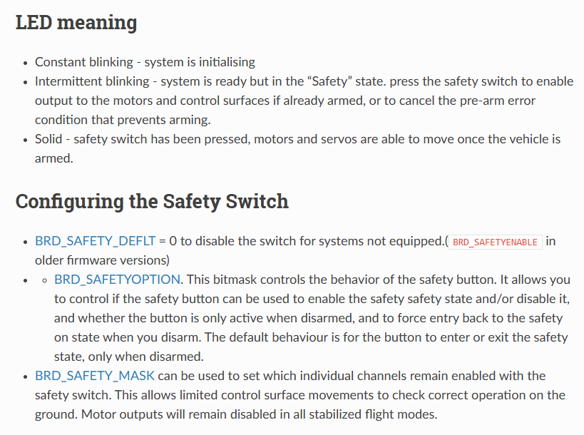
- Constant blinking - system is initialising
- Intermittent blinking - system is ready but in the “Safety” state. press the safety switch to enable output to the motors and control surfaces if already armed, or to cancel the pre-arm error condition that prevents arming.
- Solid - safety switch has been pressed, motors and servos are able to move once the vehicle is armed.
Configure the Safety Switch
- BRD_SAFETY_DEFLT = 0 to disable the switch for systems not equipped.(
<span class="pre">BRD_SAFETYENABLE</span>in older firmware versions) -
- BRD_SAFETYOPTION. This bitmask controls the behavior of the safety button. It allows you to control if the safety button can be used to enable the safety safety state and/or disable it, and whether the button is only active when disarmed, and to force entry back to the safety on state when you disarm. The default behaviour is for the button to enter or exit the safety state, only when disarmed.
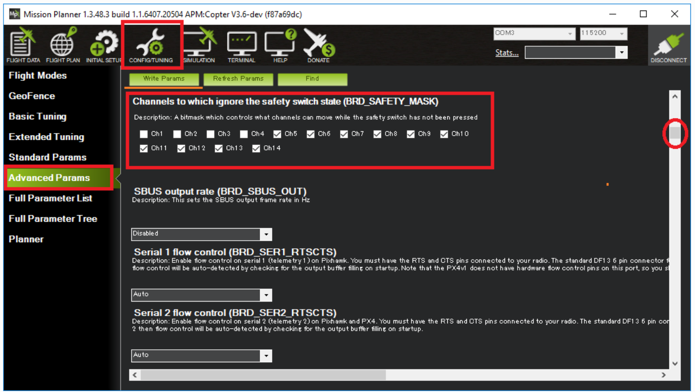
- BRD_SAFETY_MASK can be used to set which individual channels remain enabled with the safety switch. This allows limited control surface movements to check correct operation on the ground. Motor outputs will remain disabled in all stabilized flight modes.
Part 2: The Relay Driver (Actuating the Mission)
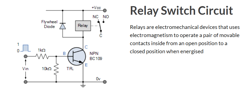
If we want to trigger a payload drop mechanism, we need a relay. The main MCU operates at 3.3V and outputs only a few milliamps. It physically cannot drive a mechanical relay coil directly without burning out the pin.
To solve this, I designed an isolated Relay Driver circuit. As seen in my schematic, we use a transistor (Q2 and Q3) as a digital switch. When the MCU sends a HIGH signal to the transistor's gate or base, it turns on, allowing a larger 5V current to flow through the relay coil and activate our payload.
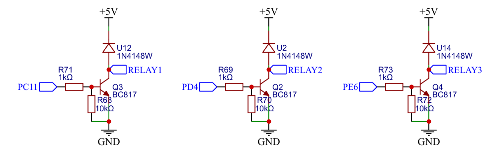
One absolutely critical component you will see in my schematic is the 1N4148W flyback diode (labeled D2 and D3). When the relay coil turns off, the collapsing magnetic field generates a massive high-voltage spike that will travel backwards and destroy the transistor or MCU. We place the 1N4148W diode in reverse-bias directly across the relay coil.
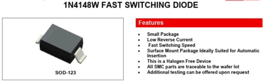
If you check a standard 1N4148W datasheet, you will see it has an ultra-fast reverse recovery time of just 4ns! This means it acts instantly to clamp and safely dissipate the destructive energy before it can damage the system.
You can check on this website for an amazing, highly trusted breakdown of how this transistor logic works: Electronics Tutorials: Relay Switch Circuit.
To see exactly what happens to a circuit when you forget this crucial component, you can see in this video from YouTube: Flyback Diodes in Relay Circuits Explained.
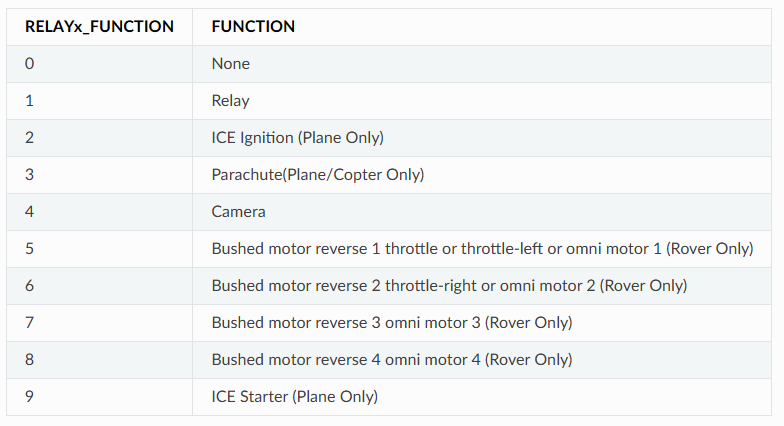
Part 3: Software Configuration for Missions
In ArduPilot, we map the MCU pin connected to our transistor as a "Relay Pin." Once mapped, we can assign an RC channel (Auxiliary Switch) on our radio transmitter to trigger this relay in mid-air. Even better, for autonomous payload dropping missions, we can insert a DO_SET_RELAY command directly into our GPS waypoint mission. The drone will fly to the target coordinate and automatically trigger the hardware we just designed!
You can check on this website for the official documentation on setting this up: ArduPilot Relay Switch Documentation.
Sign In Or Register Comment after
No comments yet. Be the first to comment!