


ESD Protection and VBUS Filtering in Flight Controllers - Part 2
 View
View
PCB Routing: The Rules of High-Speed Data
Having the USBLC6-2P6 in your schematic is only 50 percent of the battle. The way you physically draw the copper traces on your PCB dictates whether the protection will actually work.
When laying out a Flight Controller, the USB data lines (D+ and D-) must be routed as a differential pair. This means the two copper traces must travel exactly parallel to each other, maintaining a strict 90 Ohm differential impedance. If you make one trace longer than the other, or if you space them incorrectly, the USB signal will bounce back and forth, causing your computer to say "USB Device Not Recognized."
Furthermore, the USBLC6-2P6 must be placed physically as close to the USB Type-C connector as humanly possible. If you place the protection diode near the microcontroller instead of the connector, the ESD spike will travel across the entire length of your circuit board, radiating massive electromagnetic interference into your gyroscopes and barometers before it finally gets clamped.
You must also never use a "via" (a hole that goes through the layers of the PCB) on the USB traces before they hit the protection diode. Vias add inductance, which slows down the clamping response time. The raw copper trace must go straight from the connector pin, into the diode pad, and then proceed to the MCU.
Drop a comment below if you want me to do a dedicated post on how to use your PCB layout software's impedance calculator to achieve the perfect 90 Ohm differential pair routing!
Hardware Defense Part 2: Taming the Noisy VBUS
Protecting the data communication lines ensures the brain of the drone can talk to the computer. But what about the power? We also need to carefully manage the 5V power coming from your computer cable, which is known on the schematic as VBUS.
Many people assume that the USB port on their expensive laptop outputs a perfectly clean, flat 5V DC signal. This is completely false. The 5V supplied by a standard PC motherboard or a cheap external USB hub is notoriously "dirty." It is generated by noisy switch-mode power supplies inside the computer, meaning the power is full of high-frequency noise, voltage ripples, and AC hum.
If we take this dirty 5V VBUS power and feed it directly into the Flight Controller's internal 3.3V Low Drop Out regulators, that noise does not just disappear. It bleeds straight through the regulator. This electrical noise will violently fluctuate the reference voltages used by the sensitive analog measurements of our gyros, accelerometers, and barometers. If you have ever plugged in your drone to Betaflight or ArduPilot and noticed your 3D model twitching randomly even though the drone is sitting perfectly still on your desk, dirty VBUS power is often the culprit!
The LC Pi-Filter Solution
To solve this noise problem and guarantee absolute stability, I designed a robust LC low-pass filter network specifically on the VBUS input line.
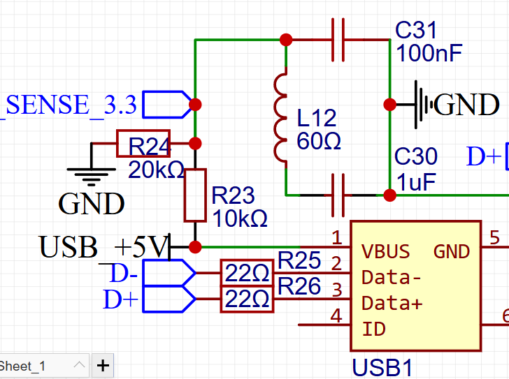
Before the raw 5V from the computer is allowed to reach the rest of the board (where it becomes the VBUS_IN net), it must pass through a gauntlet of components. The first component is an inductor, specifically a Ferrite Bead (labeled L1 on the schematic).
A ferrite bead is a fascinating component. At low frequencies (like pure DC power), it acts just like a normal piece of wire, allowing the 5V current to pass through freely. But at high frequencies (like the electrical noise generated by computer power supplies), the ferrite material actively resists the current. It literally absorbs the high-frequency electrical noise and safely dissipates it into the surrounding air as microscopic amounts of heat.
However, a ferrite bead alone is not enough. I combined this bead with two stages of capacitance. First, I placed a massive 10uF ceramic bulk capacitor. This acts as a localized energy reservoir, smoothing out any large voltage dips or low-frequency ripples from the computer. Second, I placed two 100nF ceramic decoupling capacitors directly adjacent to it. Because smaller capacitors have a lower Equivalent Series Resistance at high frequencies, the 100nF capacitors are perfectly tuned to absorb ultra-fast voltage spikes that the 10uF capacitor is too slow to catch.
Together, the Ferrite Bead, the 10uF capacitor, and the 100nF capacitors create an impenetrable LC filter. They take the chaotic, noisy power from your computer and transform it into a perfectly flat, clean, and safe 5V supply for the rest of your sensitive aviation hardware.
For an incredible visual explanation of how to design a robust USB hardware interface from scratch, including the math behind the TVS diodes and VBUS filtering we just discussed, you can see in this video from Phil's Lab on YouTube: https://youtu.be/W13HNsoHj7A?si=HAqM2yn2nMLlvtp2. He is a phenomenal resource for professional PCB design and watching him route these exact components is highly educational.
Sign In Or Register Comment after
No comments yet. Be the first to comment!