


Designing UART Ports for RC Receivers and Telemetry (Part 1)
 View
View
Today, we are going to look specifically at the TELEME and RCIN blocks in my schematic. I will explain in detail how to design UART ports that are exceptionally robust. This design not only protects your microcontroller from physical electrical damage but also guarantees flawless data communication with your Radio Control receiver and your high power LoRa telemetry modules.
UART
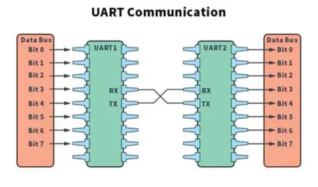
Before we dissect the specific ports on the board, we must understand the underlying protocol. UART stands for Universal Asynchronous Receiver Transmitter. This protocol relies on two primary data lines, which are TX for Transmit and RX for Receive. When you connect any external module to the Flight Controller, you must always cross these communication lines. The TX pin of the external module connects to the RX pin of the Flight Controller, and the same rule applies in reverse.
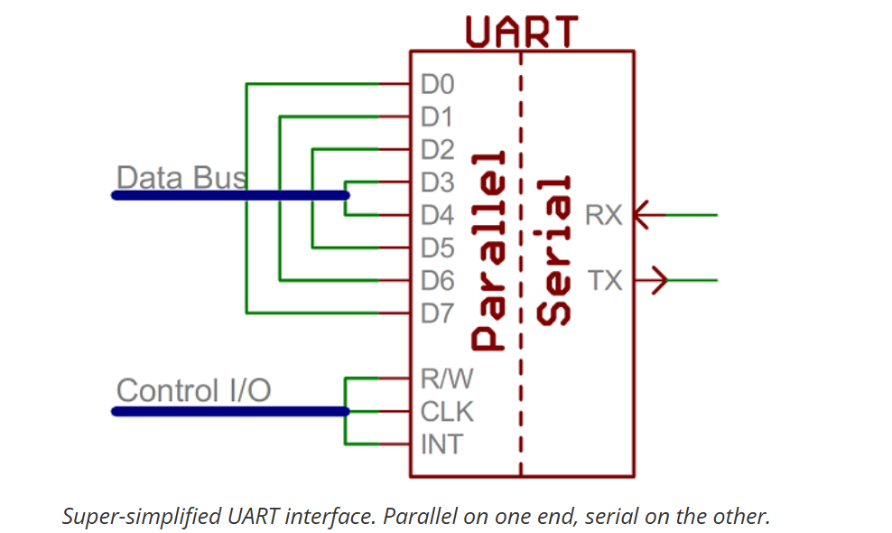
If you want to understand the fundamental mechanics of serial communication at the hardware level, you can check on this website from SparkFun: SparkFun Serial Communication Tutorial. They offer a highly trusted explanation regarding how digital data packets are constructed and transmitted.
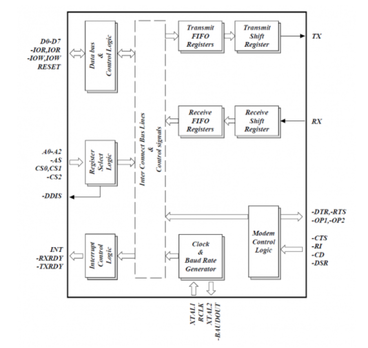
This images shown exactly how the internal shift registers handle the raw serial data stream.
Designing the TELEME Port for LoRa Telemetry
The TELEME port on my Flight Controller is designed specifically to connect to external radio telemetry modules. These modules are frequently high power LoRa radios that constantly broadcast flight data back to a laptop on the ground. Designing this port requires strict attention to power delivery stability and digital signal integrity.
1. Power Stability and Capacitive Filtering
Telemetry radios draw massive surges of current when they transmit data packets. If you power a 1 Watt radio directly from the same 5V line as your main MCU without adequate filtering, the rapid voltage drops will cause the microcontroller to reboot mid flight.
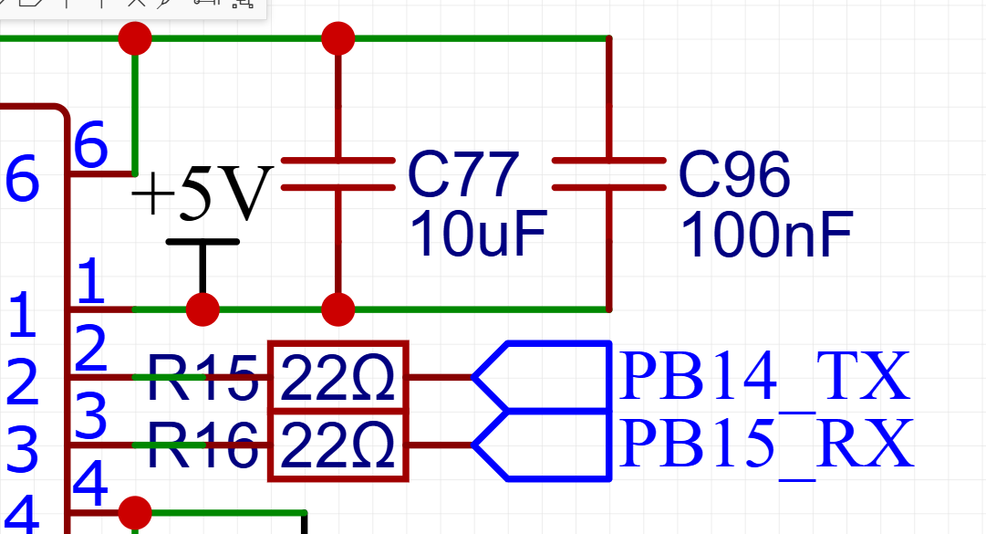
In my schematic, I ensure the TELEME port features a highly robust filter network. I implemented a 10uF bulk capacitor paired with a 100nF ceramic decoupling capacitor, placing both exactly next to the telemetry power pin. The 10uF capacitor acts as a localized energy reservoir to absorb the sudden current draw, while the 100nF capacitor actively filters out high frequency electrical noise. This combination guarantees the power plane remains absolutely stable.
2. Signal Integrity with 22 Ohm Resistors
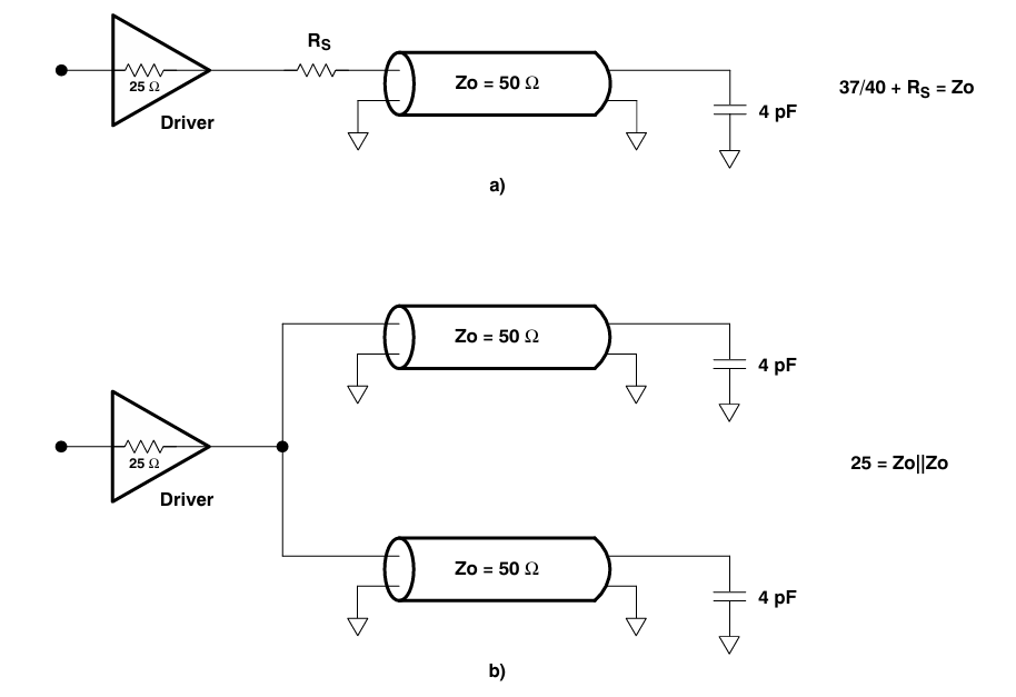
High speed digital signals traveling across a printed circuit board can behave like radio waves. If the signal is too strong or the copper trace is too long, the signal will hit the end of the wire and bounce back. This creates reflections and ringing that corrupt the data integrity.
To prevent this, I placed a 22 Ohm series resistor on both the TX and RX lines at the TELEME port. This electrical technique is known as source termination. The 22 Ohm resistor absorbs the reflected energy and slightly slows down the rising edge of the digital signal. This approach heavily reduces electromagnetic interference and guarantees that your telemetry data reaches the LoRa module with maximum clarity.
You can check on this website for an outstanding academic discussion regarding how termination resistors work in digital electronics: Texas Instruments Termination Guide.
Sign In Or Register Comment after
No comments yet. Be the first to comment!