


DIY Current Meter using a Ferrite Core and Hall Sensor
 View
View
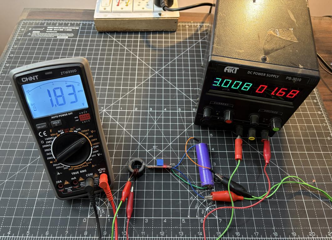
I built a DC ammeter using a toroidal ferrite core and a Hall Effect sensor (WSH130NL). The idea is, when current flows through a wire around a toroidal core, it creates a magnetic field inside the core. For AC measurements we can just use a secondary winding and get a pretty good step down transformer producing an effective voltage which can be converted into current values. But with a DC steady signal we have to measure the magnetic flux in a different manner. Overall now with this approach we get an isolated current measurement. And by choosing the right number of windings, you can adjust the sensitivity and resolution of your ammeter to suit your needs. The same can be converted later with the help of a PCB provided by JLCPCB. As I got my MCU dev board fabricated from there in a $2 price. See the full article with code from here: https://www.hackster.io/sainisagar7294/diy-current-meter-using-a-ferrite-core-and-hall-sensor-4a91aa
How Does It Work?
When current passes through a conductor coiled around a toroidal ferrite core, it generates a magnetic field within the core. Due to the ferrite’s high permeability, the magnetic field is largely confined inside the core. By placing a Hall Effect sensor in the air gap, the sensor is positioned directly in the path of the magnetic flux. It then generates a voltage proportional to the magnetic field passing through it.
Components Required
WSH130NL Hall Effect Sensor
Toroidal Ferrite Core
Enamelled Copper Wire
10K Ohm Resistor
0.1uF Capacitor
Arduino Uno/Nano
16x2 LCD Display I2C
Building the DC Ammeter - Step by Step
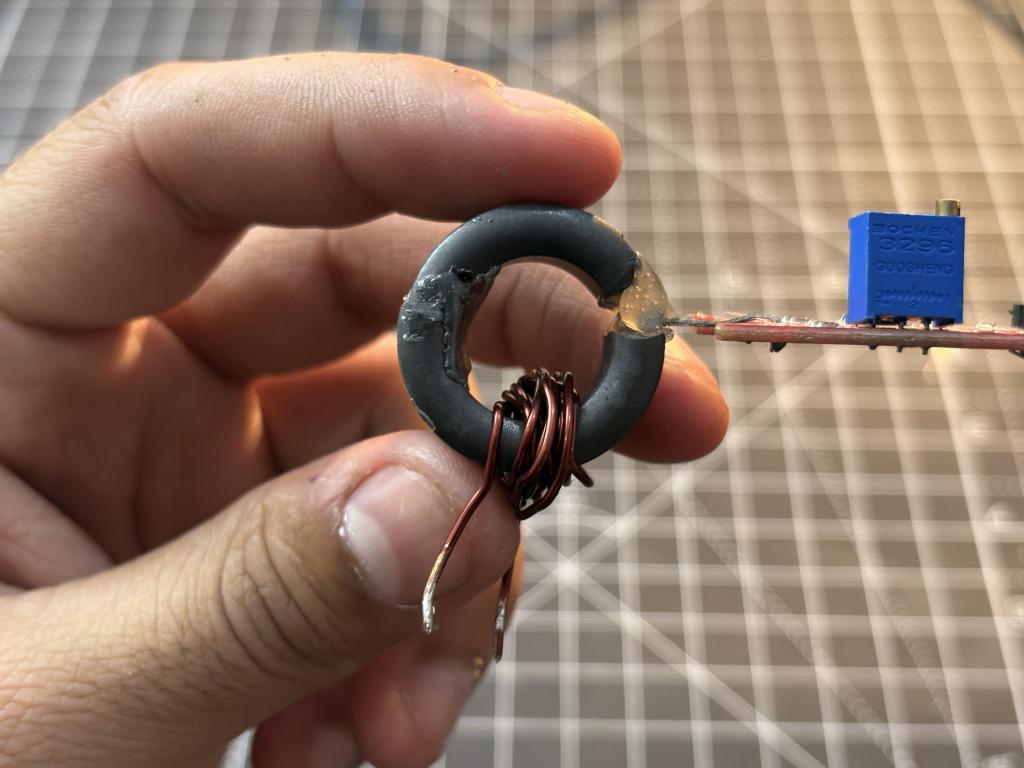
The toroidal ferrite core is the heart of this ammeter. You can salvage one from an old power supply, a common-mode choke, or buy one online. The size doesn't matter too much, but a larger core gives you more room to wind wires.
Cutting the Air Gap:
This is the most critical and tricky step. We need to cut a small gap in the toroid where the Hall sensor will sit.
Winding the Toroid:
I used 10 turns of 24 AWG enamelled copper wire on a ferrite core. More windings mean a stronger magnetic field for the same current.
Placing the Hall Effect Sensor:
You can place the sensor, make sure it is flat in the middle of the gap, then secure it using hot glue and some tape. The orientation decides the polarity, but it doesn't matter even in this case because the steady state sensor readings are common mode by VDD/2.
Arduino Code:
The Arduino's 10-bit ADC gives us 1024 steps across 0-5V, which translates to approximately 4.88mV per step.
How to Calibrate:
- Upload the code to your Arduino with SENSITIVITY set to 0 initially
- With no current flowing, write down value of V_OFFSET.
- Pass a known current of say 1A and note the voltage.
- Pass another known current of 3A, note the voltage
- Update the V_OFFSET and SENSITIVITY defines in the code
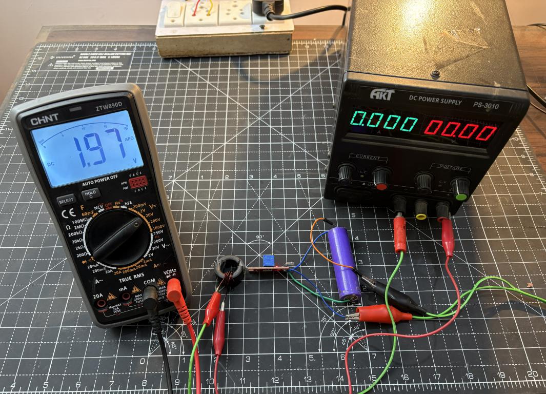
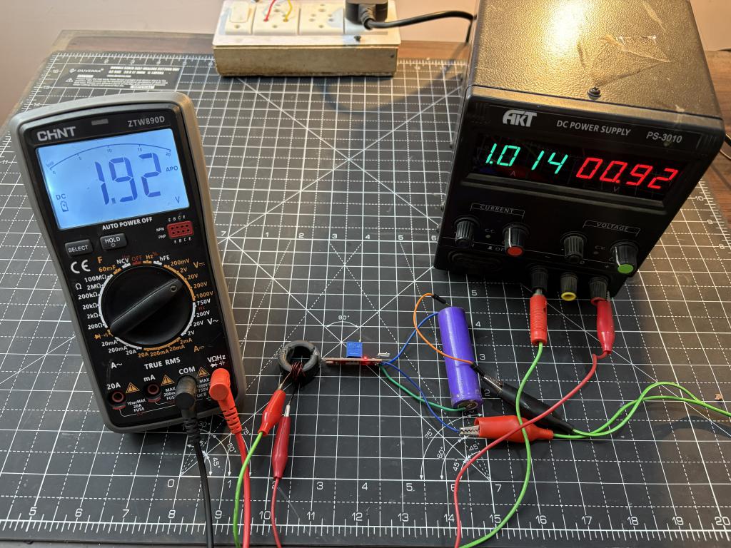
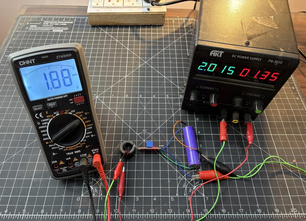
Working:
At 0A:
At 1A:
At 2A:
At: 3A:
#HallEffect# #PCB# #currentmeter# #powermeter# #Arduino#
 #HallEffect#
#PCB#
#currentmeter#
#powermeter#
#Arduino#
#HallEffect#
#PCB#
#currentmeter#
#powermeter#
#Arduino#
Sign In Or Register Comment after
No comments yet. Be the first to comment!