


Practical Guide: How to Select a Supercapacitor Bank with a 12V Battery System
 View
View
In a real supercapacitor vs battery design, the goal is to choose a supercapacitor that can handle startup current spikes without causing voltage sag or stressing the battery. Selection is based on three parameters: voltage, capacitance, and ESR.
1. Voltage Rating (Series Cells)
Supercapacitors are rated ~2.5–2.7V per cell, so series connection is required.
- 12V system peak ≈ 14.4V
- Required cells: 14.42.7≈ 6
Design choice:
- Use 6–8 cells in series (≈16V rated bank)
- Include cell balancing (passive or active) to prevent overvoltage
2. Capacitance (Farad Selection)
Capacitance determines how effectively voltage sag is reduced during transients.
Note: Despite high capacitance (F), supercapacitors store less energy than batteries due to lower voltage.
Quick sizing guideline:
- Small loads → 0.1–1 F
- Medium loads → 1–10 F
- High surge (motors, inverters) → 10–50 F+
Oversize by ~2× for stability and aging margin
3. ESR (Critical for High Current)
Voltage drop under load: V=I×ESR
Example: 20A × 0.1Ω = 2V drop (unacceptable for 12V rail)
Target ESR:
- Moderate load → < 50 mΩ
- High surge → < 10–20 mΩ
4. Choosing Supercapacitor Type
- Cylindrical EDLC cells → best flexibility and performance
- Pre-balanced modules → simpler integration for higher voltage systems
5. Pre-Charge the Supercapacitor Bank (Critical Step)
A discharged supercapacitor behaves like a near short circuit, causing dangerous inrush current if directly connected.
Procedure:
Step 1: Insert a pre-charge element
- Power resistor (5–50Ω, high wattage) or NTC thermistor
Step 2: Estimate initial current: I_initial=V✖R
- Example: 12V / 10Ω ≈ 1.2A (safe)
Step 3: Allow gradual charging:
- Time constant: τ=R✖C
Step 4: Monitor voltage
- Wait until: Supercapacitor voltage ≈ battery voltage (within ~0.1–0.2V)
6. Switch to Direct Parallel Connection
Once pre-charged:
-
Bypass the resistor using:
- Relay / contactor (simple)
- MOSFET switch (preferred for modern systems)
*******Connection sequence:
- Pre-charge through resistor
- Verify voltage match
- Close bypass switch
→ Supercapacitor now directly in parallel
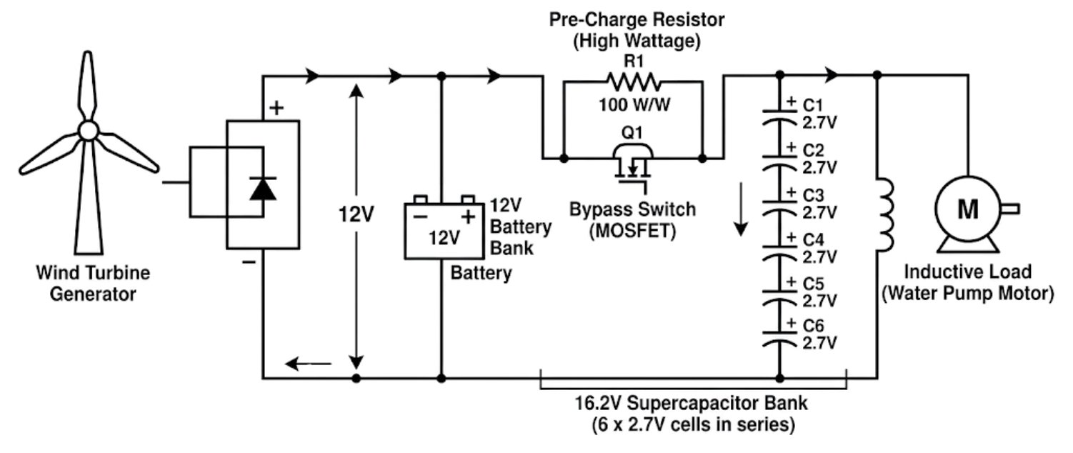
Figure: Circuit schematic of a 12V wind turbine hybrid power system. It details a 12V battery connected in parallel with a 6-cell supercapacitor bank, featuring a current-limiting pre-charge resistor and a bypass switch to safely manage inrush current.
⚠️ Engineering Notes
-
Never connect a 0V supercapacitor directly to a battery
-
Use proper wire gauge (high current path)
-
Keep connections short (minimize inductance)
-
Add protection:
- Fuse or current limiting if required
\
Result
-
Supercapacitor handles startup surge current
-
Battery provides continuous energy
-
System avoids:
- voltage sag
- battery stress
- premature degradation
Key Takeaway: Always pre-charge a supercapacitor before connecting it in parallel with a battery - this prevents destructive inrush current and ensures stable hybrid operation.
Learn More: https://jlcpcb.com/blog/supercapacitor-vs-battery
**##supercapacitor# ##battery# ##supercapacitor_vs_battery#**
 #supercapacitor#
#battery#
#supercapacitor_vs_battery#
#supercapacitor#
#battery#
#supercapacitor_vs_battery#
Sign In Or Register Comment after
No comments yet. Be the first to comment!