


Voltage converter 12V Into Dual-Rail 24V
 View
View
I do love making circuits that can power my car amplifier from my car battery. Not just because it is 12V but my amplifier system needs a dual rail power. This is the major problem in transistor based amplifiers because they need a higher voltage with a stable ground reference thus a dual rail power supply concept comes and it hurts me more when I just have a simple 12V battery. Something like +24V and -24V. You need a way to step that up and split it into two symmetric rails. The obvious thing that came to mind is using a transformer that can do it.
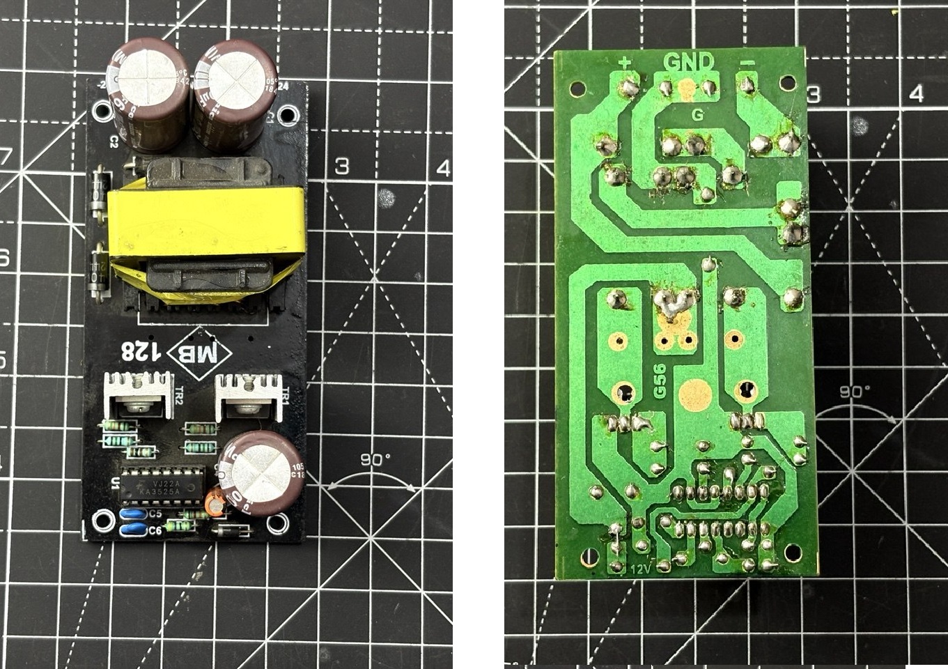
That's exactly what this module does. It's a pre-built push-pull DC-DC converter board that takes 12V DC in and outputs 24-0-24V (that's +24V and -24V with a centre-tap ground) at over 5A. I picked one up for an amplifier project, and I thought it was worth breaking down how it actually works. The controller IC running the show is the KA3525A, a classic SMPS controller that has been around for decades. I will show here how the push-pull topology works, and how to wire it up safely. For real-world power-on and load testing.
How to Use It:
Connect your 12V DC source to the input terminals. This module does not have a reverse voltage protection feature. Use a source capable of supplying enough current. At 5A output on the 24V rails, the input side draws significantly more 10-12A from the 12V supply due to the step-up ratio plus conversion losses. Use thick wires (at least 14-16 AWG) and a source rated accordingly. A 12V lead battery or a beefy 12V switching adapter works well. Avoid unregulated wall warts.
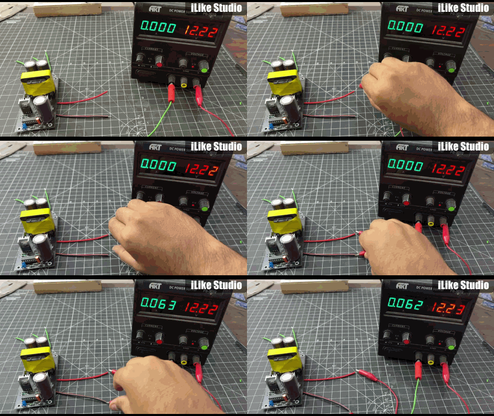
Connect +24V and -24V to your amplifier's V+ and V- supply pins. The 0V centre-tap connects to your amplifier's ground. Some push-pull converters can develop voltage at no-load because the feedback loop. Start with a light load and verify the output voltages with a multimeter before connecting your amplifier.
My Experience:
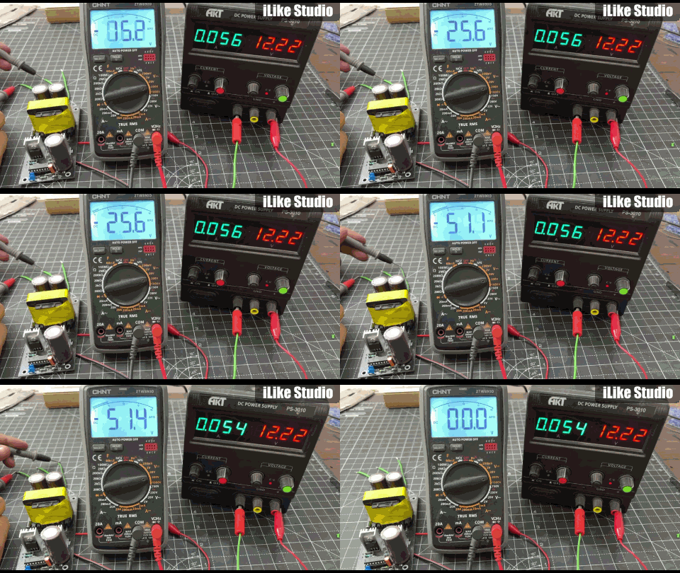
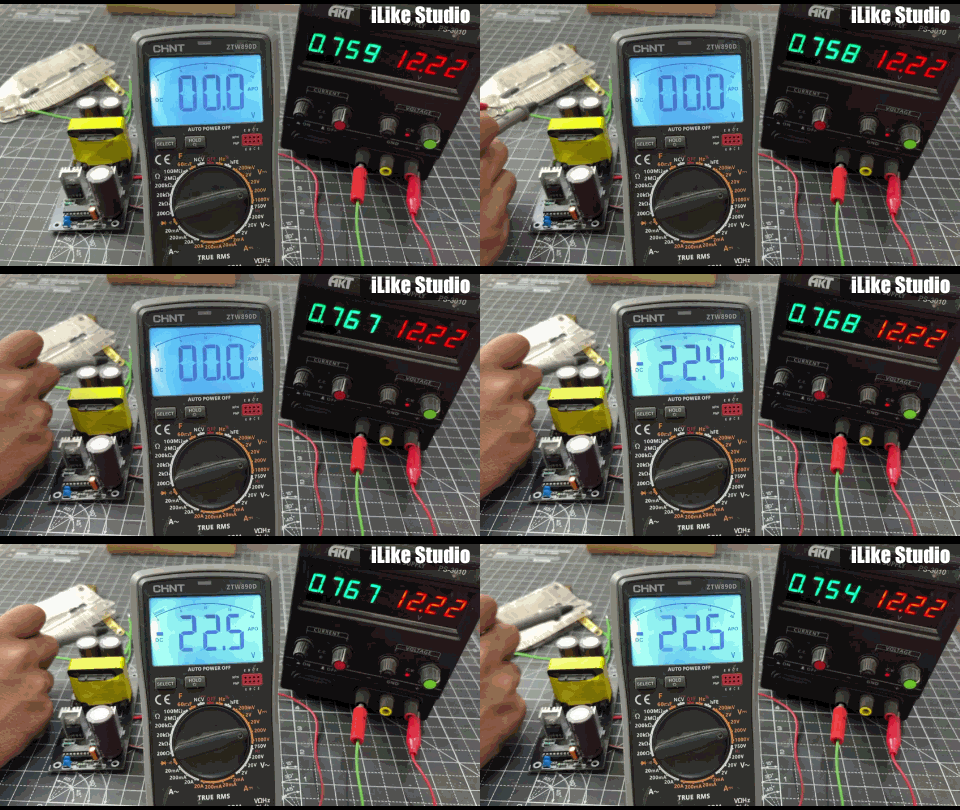
I got this module to pair with an audio amplifier that needed dual +/-24V rails but I only had a 12V bench supply handy. It delivered on its core promise stable +/-24V rails from 12V input, powering the amplifier, I have checked it using a multimeter. As the output capacitor charges it shows a significantly higher around 25V. But I have also tested it under some load for which the results are given here.
Build quality is what you'd expect from a generic module. The PCB is decent, solder joints are acceptable, and the IRFZ44N MOSFETs are genuine. The transformer is the biggest component on the board and it's wired reasonably well. What you need to find is just a good component vendor in case you are building something like this on your own.
#power convertor# #voltageConvertor# #PCB#
 #powerconvertor#
#voltageConvertor#
#PCB#
#powerconvertor#
#voltageConvertor#
#PCB#
Sign In Or Register Comment after
No comments yet. Be the first to comment!