


How to Measure AC Current Using CT Sensors: A Practical Guide
 View
View
Current Transformer (CT) sensors are widely used for measuring AC current in industrial and embedded systems. They provide electrical isolation and allow high current measurement without direct electrical contact with the conductor.
This guide explains how to properly use CT sensors with microcontrollers for accurate current measurement.
How CT Sensors Work
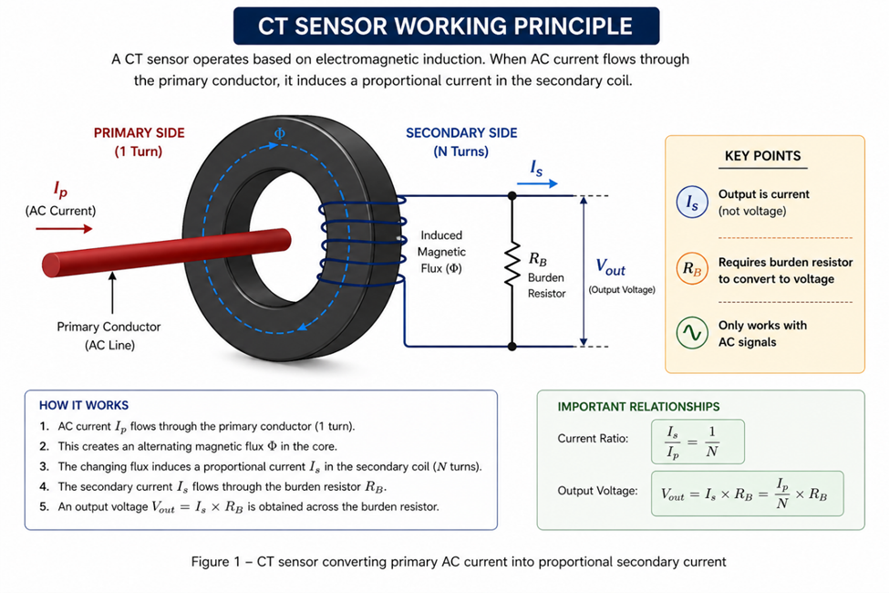
A CT sensor operates based on electromagnetic induction. When AC current flows through the primary conductor, it induces a proportional current in the secondary coil.
Key points:
- Output is current (not voltage)
- Requires burden resistor to convert to voltage
- Only works with AC signals
Basic Connection to Microcontroller
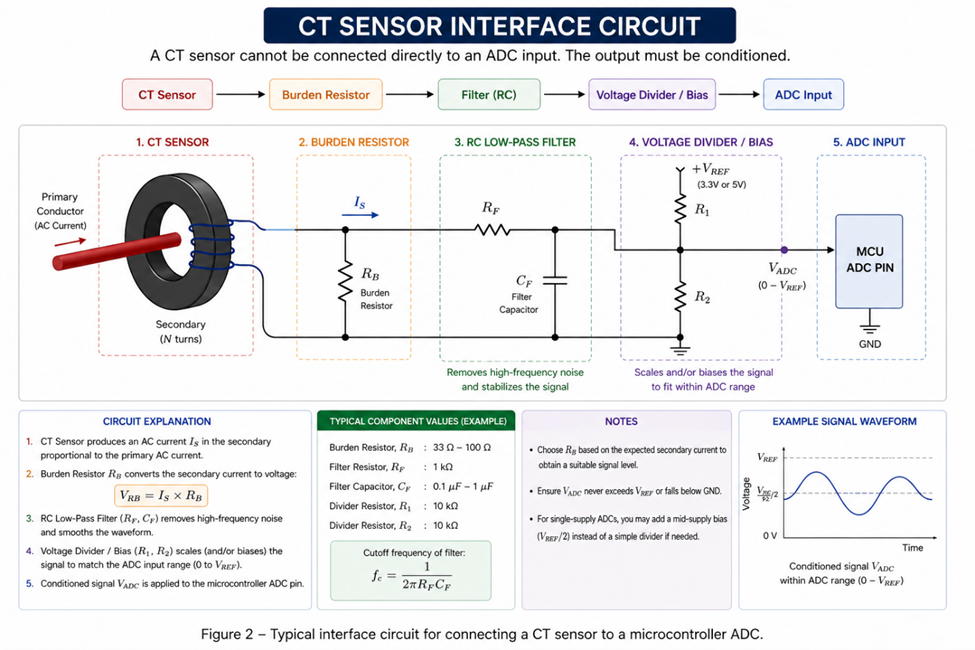
A CT sensor cannot be connected directly to an ADC input. The output must be conditioned.
Required components:
- Burden resistor
- RC low-pass filter (optional)
- Voltage divider / biasing (for ADC protection)
Basic flow:
CT Sensor → Burden Resistor → Filter → ADC Input
Burden Resistor Selection
The burden resistor converts CT output current into measurable voltage.
Formula:
Where:
Selection considerations:
- Output voltage must stay within ADC range (0–3.3V / 5V)
- Too large → saturation
- Too small → low resolution
Proper selection is critical for measurement accuracy.
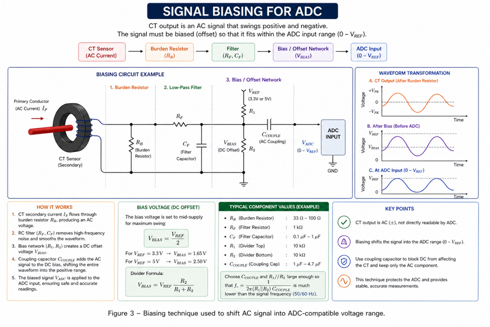
Signal Conditioning and Offset
Because CT output is AC (positive & negative), ADC input must be adjusted.
Common approach:
- Add DC offset (bias) to shift signal into positive range
- Use capacitor filtering to stabilize waveform
This ensures safe and stable ADC readings.
RMS Calculation Implementation
After signal acquisition:
- Sample ADC values continuously
- Convert to voltage/current
- Apply RMS calculation
- Display or log results
To improve accuracy:
- Use multiple sampling cycles
- Apply filtering
- Calibrate scaling factor
Common Mistakes
Avoid these common issues:
- ❌ No burden resistor (dangerous for CT)
- ❌ Direct connection to ADC
- ❌ Incorrect resistor value
- ❌ Ignoring signal offset
- ❌ Low sampling rate
These mistakes can cause inaccurate readings or hardware damage.
Practical Applications
CT sensors are commonly used in:
- Energy monitoring systems
- Industrial load measurement
- Smart meters
- Motor current monitoring
- Data logging systems
Conclusion
CT sensors provide a safe and effective method for measuring AC current in embedded systems. With proper signal conditioning, correct burden resistor selection, and accurate RMS calculation, reliable current measurement can be achieved for both industrial and IoT applications.
#Sensors#
#CTSensor#
#CurrentMeasurement#
#EmbeddedSystem#
#AnalogSignal#
#TestAndMeasurement#
 #Sensors#
#CTSensor#
#CurrentMeasurement#
#EmbeddedSystem#
#AnalogSignal#
#TestAndMeasurement#
#Sensors#
#CTSensor#
#CurrentMeasurement#
#EmbeddedSystem#
#AnalogSignal#
#TestAndMeasurement#
Sign In Or Register Comment after
No comments yet. Be the first to comment!