


How ADC Works in Microcontrollers (Simple Explanation)
 View
View
Analog signals such as temperature, voltage, and current cannot be processed directly by microcontrollers because they operate digitally. To convert analog signals into digital values, an Analog-to-Digital Converter (ADC) is used.
This article explains how ADC works in microcontrollers and how it is used in practical applications.
What is ADC?
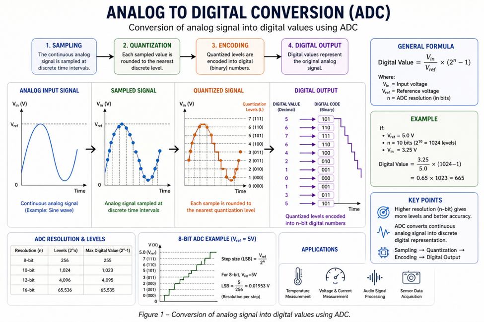
ADC (Analog-to-Digital Converter) converts a continuous analog signal into a discrete digital value that can be processed by a microcontroller.
Example:
- 0–3.3V input → 0–4095 (for 12-bit ADC)
This allows the system to interpret real-world signals in digital form.
Basic Working Principle
The ADC samples the input voltage and converts it into a digital number based on resolution.
General formula:

Where:
- Vin = input voltage
- Vref = reference voltage
- n = ADC resolution
ADC Resolution
Resolution determines how precise the measurement is.
| Resolution | Levels |
|---|---|
| 8-bit | 256 |
| 10-bit | 1024 |
| 12-bit | 4096 |
Higher resolution → better accuracy.
Sampling Process
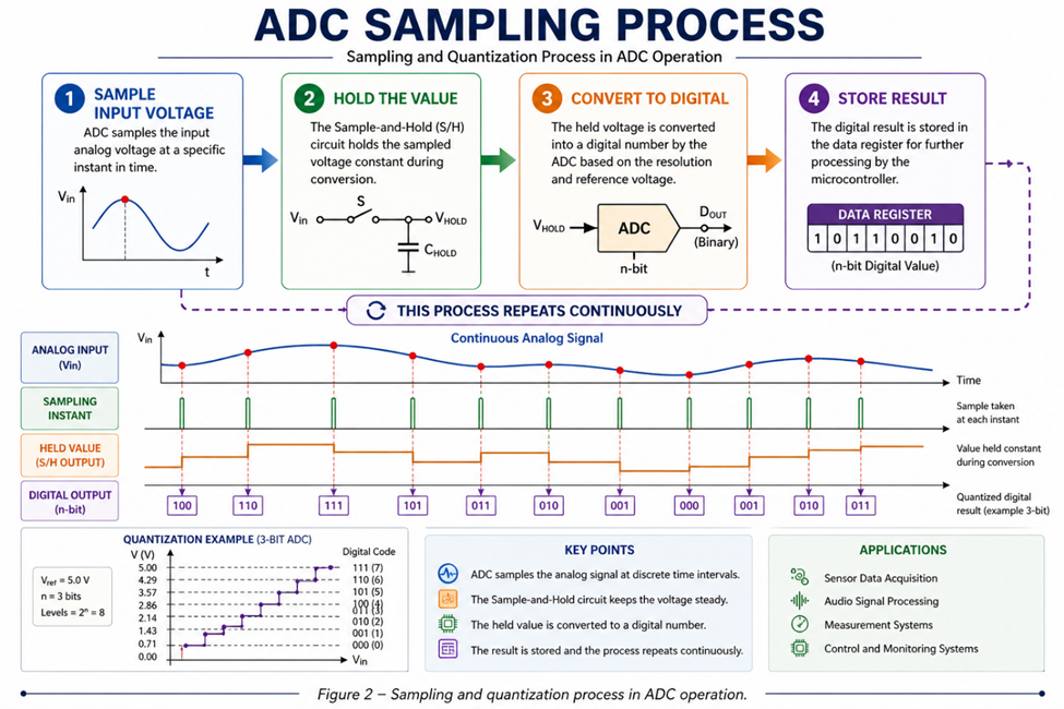
ADC works in steps:
- Sample input voltage
- Hold the value
- Convert to digital
- Store result
This process repeats continuously.
Practical Example
Using ESP32 (12-bit ADC):
- Vref = 3.3V
- Vin = 1.65V
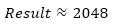
This value can be used to calculate actual voltage or sensor data.
Common Issues
- Noise affects accuracy
- Wrong reference voltage
- Poor grounding
- Non-linear ADC behavior
Practical Applications
ADC is used in:
- Voltage measurement
- Current sensing
- Temperature sensors
- Analog sensors
ADC is a fundamental component in embedded systems that enables microcontrollers to read real-world analog signals. Understanding how ADC works helps improve measurement accuracy and system performance.
#Microcontrollers#
#ADC#
#EmbeddedSystem#
#AnalogSignal#
#ElectronicsBasics#
#Arduino#
 #Microcontrollers#
#ADC#
#EmbeddedSystem#
#AnalogSignal#
#ElectronicsBasics#
#Arduino#
#Microcontrollers#
#ADC#
#EmbeddedSystem#
#AnalogSignal#
#ElectronicsBasics#
#Arduino#
Sign In Or Register Comment after
No comments yet. Be the first to comment!