


Understanding PWM for Motor and LED Control
 View
View
Pulse Width Modulation (PWM) is a widely used technique in microcontrollers to control power delivered to devices such as motors, LEDs, and heaters. Instead of changing voltage directly, PWM controls the duty cycle of a digital signal to simulate analog output.
What is PWM?
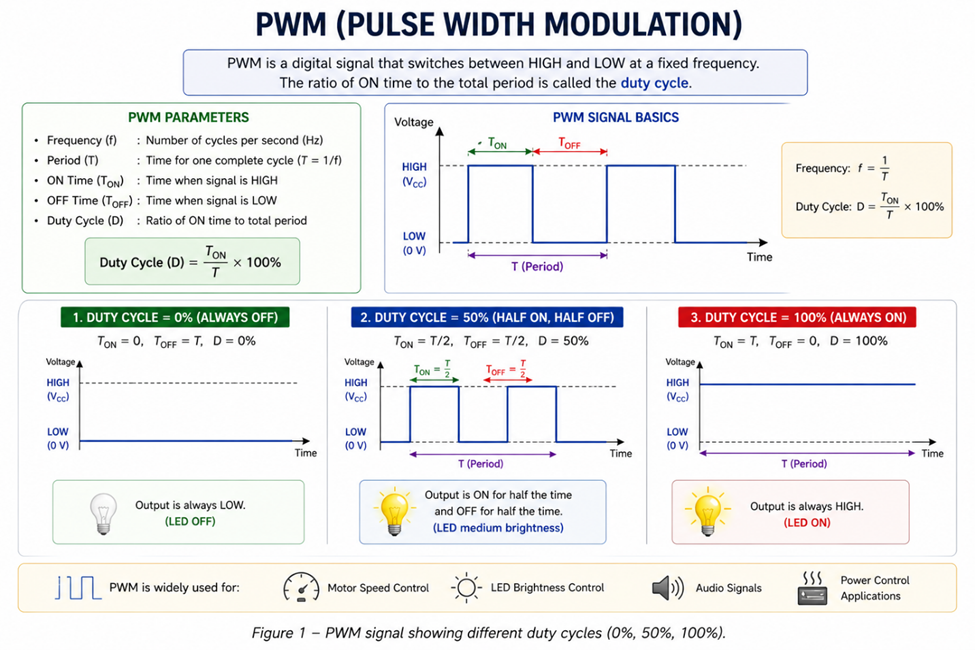
PWM is a signal that switches between HIGH and LOW at a fixed frequency. The ratio of ON time to total period is called the duty cycle.
- 0% → always OFF
- 50% → half ON, half OFF
- 100% → always ON
How PWM Controls Output
Even though PWM is digital, devices respond to the average power.
Example:
- LED → brightness changes
- Motor → speed changes
Higher duty cycle → more power delivered.
PWM Parameters
Key parameters:
- Frequency → how fast signal switches
- Duty Cycle → percentage of ON time
Both affect system behavior.
PWM for LED Control
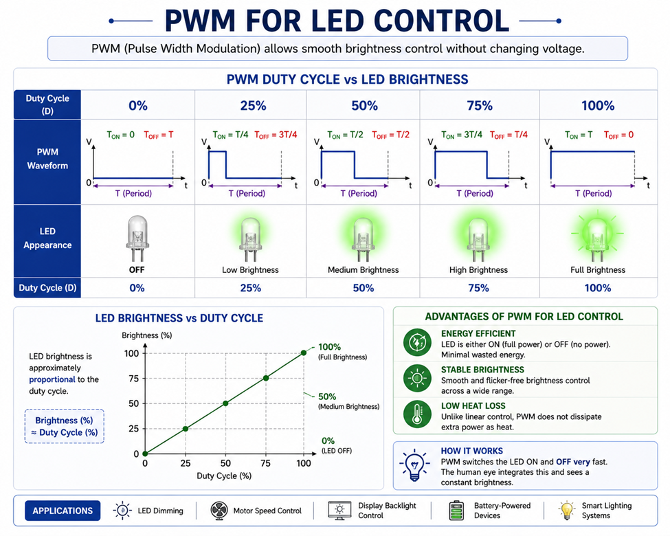
PWM allows smooth brightness control without changing voltage.
Advantages:
- Energy efficient
- Stable brightness
- No heat loss like linear control
PWM for Motor Control
PWM controls motor speed by adjusting average voltage.
- Low duty → slow speed
- High duty → fast speed
Used in:
- DC motors
- Fans
- Robotics
Practical Example
Using Arduino:
analogWrite(ledPin, 128); // 50% duty cycle (0–255)
Common Issues
- Wrong frequency → flickering or noise
- Low resolution → rough control
- Electrical noise in motor systems
Applications
PWM is widely used in:
- Motor speed control
- LED dimming
- Power regulation
- Switching power supplies
PWM is a powerful and efficient method to control analog behavior using digital signals. By adjusting duty cycle and frequency, microcontrollers can precisely control devices in various applications.
#Microcontrollers#
#PWM#
#EmbeddedSystem#
#MotorControl#
#LEDControl#
#Electronics#
 #Microcontrollers#
#PWM#
#EmbeddedSystem#
#MotorControl#
#LEDControl#
#Electronics#
#Microcontrollers#
#PWM#
#EmbeddedSystem#
#MotorControl#
#LEDControl#
#Electronics#
Sign In Or Register Comment after
No comments yet. Be the first to comment!