


How to Measure Voltage Using Voltage Divider and ADC
 View
View
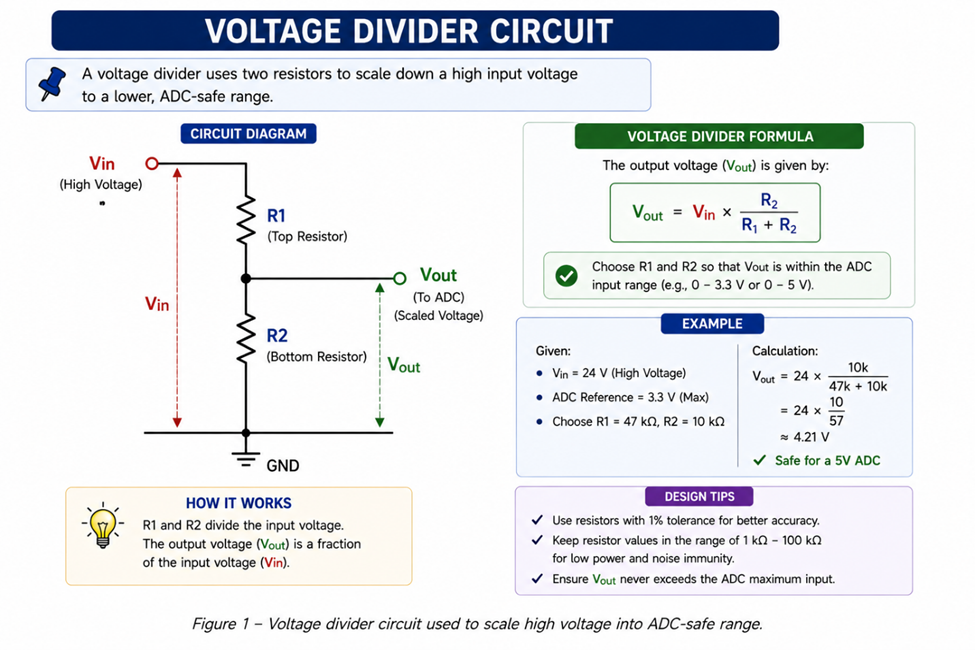
Microcontrollers cannot measure high voltages directly because their ADC (Analog-to-Digital Converter) has a limited input range, typically 0–3.3V or 0–5V. To measure higher voltages, a voltage divider circuit is used to scale the voltage down to a safe level.
What is a Voltage Divider?
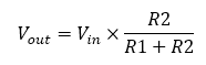
A voltage divider uses two resistors to reduce input voltage.
Formula:
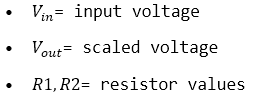
Where:
Why Voltage Divider is Needed
Directly connecting high voltage to ADC can:
- Damage microcontroller
- Produce incorrect readings
Voltage divider ensures:
- Safe input range
- Accurate measurement
Example Calculation
If measuring 12V with 3.3V ADC:
Choose:
- R1 = 10kΩ
- R2 = 3.3kΩ
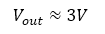
Safe for ADC input.
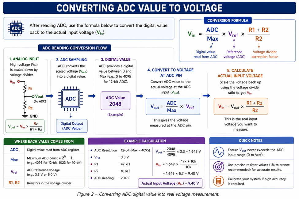
Converting ADC Value to Voltage
After reading ADC:
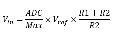
This converts digital value back to actual voltage.
Practical Considerations
- Use precise resistor values
- Avoid very high resistance (noise sensitive)
- Add capacitor for filtering
- Calibrate for accuracy
Common Mistakes
- Wrong resistor ratio
- Ignoring ADC reference voltage
- No filtering → noisy signal
- Measuring voltage above design limit
Applications
Voltage divider is used in:
- Battery monitoring
- Power supply measurement
- Solar system monitoring
- Sensor scaling
Voltage divider is a simple and essential technique for measuring higher voltages using microcontroller ADC. With proper design and calibration, it provides safe and accurate voltage measurement for embedded systems.
#TestAndMeasurement#
#VoltageDivider#
#ADC#
#EmbeddedSystem#
#Electronics#
#Arduino#
 #TestAndMeasurement#
#VoltageDivider#
#ADC#
#EmbeddedSystem#
#Electronics#
#Arduino#
#TestAndMeasurement#
#VoltageDivider#
#ADC#
#EmbeddedSystem#
#Electronics#
#Arduino#
Sign In Or Register Comment after
No comments yet. Be the first to comment!