


LM358 Based Simple Waveform Generator
 View
View
Original Hackster article: https://www.hackster.io/sainisagar7294/lm358-based-simple-waveform-generator-79af29
LM358 waveform generator — square and triangular outputs
I needed a quick bench tool to verify small circuits and ICs without spending $50+ on a function generator. So I built one from a single LM358 op-amp for square and triangular waves up to 5kHz, for under $2.
Circuit
The design uses a Schmitt trigger relaxation oscillator for the square wave. R1 controls the capacitor charge/discharge time and sets the base frequency range. R2 and R3 form a voltage divider that sets the waveform midpoint reference (the ground line). A 100kΩ potentiometer makes frequency variable within the range.
A series RC integrator (R4 + C2) converts the square output into a triangular wave. The RC time constant must be larger than the square wave period, otherwise the capacitor does not have enough time to form a clean ramp.
Amplitude vs. Frequency
The triangular wave amplitude is inversely related to frequency. At low frequencies, the capacitor charges more per half-cycle and gives a larger swing. At high frequencies, it barely charges before polarity flips and the output shrinks. This is inherent to RC integration. Adding a second integrator stage approximates a sine wave, but amplitude drops sharply above 1kHz. For stable sine output, a Wien bridge or Hartley oscillator is the better choice.
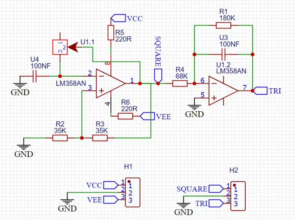
Schematic — square wave generator with RC integrator
Components and PCB
Components needed:
• LM358 op-amp
• Resistors: 180kΩ, 68kΩ, 39kΩ, 220Ω
• 100nF capacitor
• 100kΩ potentiometer
• Dual-rail power supply
PCB designed in EasyEDA. Square wave amplitude scales with supply voltage. For a fixed-amplitude triangular output, add a third op-amp gain stage on the output. Gerbers available in the original article, change R1/C1 values to shift the frequency range.
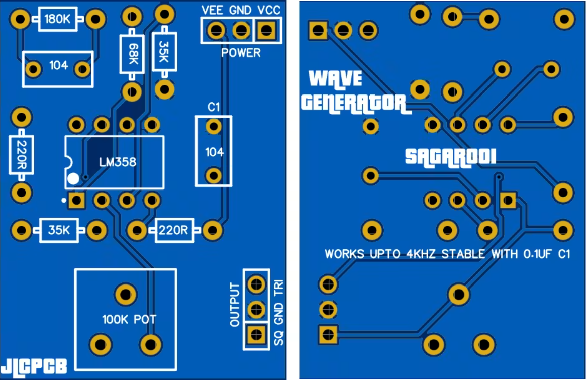
PCB prototype — both outputs tested
Sign In Or Register Comment after
No comments yet. Be the first to comment!