


PCB Trace Current Carrying Capability
 View
View
How wide does this trace need to be? Get it wrong, too narrow for the current it carries. And the trace becomes a resistive heater: voltage drop, heat buildup, and eventually an open circuit. IPC-2221 is the standard that gives you the answer.
IPC-2221 Quick Reference
IPC-2221 provides empirical tables relating trace width, copper weight, and current capacity at a target temperature rise. A 10°C rise above ambient is a safe working limit for most designs.
1oz copper (35μm), external trace, 10°C rise:
• 0.5mm → ~0.9A
• 1.0mm → ~1.5A
• 2.0mm → ~2.7A
• 3.0mm → ~3.6A
Internal traces handle roughly 50–60% of the above values for the same width, they are buried in FR4 with no air cooling available.
Copper Weight
Standard PCB copper is 1oz (35μm per layer). Moving to 2oz doubles the cross-section and increases current capacity by roughly 40–50% for the same trace width. Heavy copper (3oz, 4oz+) is used in power converters and motor drives where 10A+ traces are needed. JLCPCB supports copper up to 13oz for specialty power PCBs.
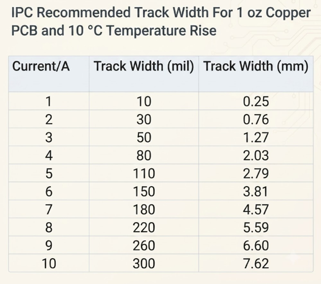
Width vs. current chart — 1oz external traces (IPC-2221)
Layout Rules
Practical rules to follow during layout:
• Add a copper pour on top of high-current traces to double the effective cross-section without widening the routed track
• Use Saturn PCB Design Toolkit or JLCPCB's trace width calculator becausee IPC-2221 formulas are non-trivial to compute by hand
• JLCPCB's standard trace width tolerance is ±20%: a 1mm trace could be 0.8–1.2mm in production
• Always check voltage drop, not just thermal capacity: 2A through 100mm of 1mm 1oz trace drops about 68mV which is significant in low-voltage designs
Sign In Or Register Comment after
No comments yet. Be the first to comment!