


One-Button USB-C PD Voltage Selector with CH224K and CH32V003
 View
View
Original Instructables article: https://www.instructables.com/One-Button-Based-5-20V-USB-C-PD-Voltage-Selector/
I have worked with the CH224K USB PD sink controller before, a tiny IC that handles the entire PD negotiation for you. My previous build used fixed resistors to set the voltage. This time I wanted something more practical: a single-button selector that cycles through 5V, 9V, 12V, 15V, and 20V with LED indicators for each. The MCU I paired it with is the CH32V003F4P6 — a 32-bit RISC-V chip from WCH that costs about $0.10.
How It Works
The CH224K handles USB PD negotiation over the CC lines in the USB-C connector. Three configuration pins (CFG1, CFG2, CFG3) tell it which voltage to request from the charger. Drive these with a microcontroller and you can change voltage on the fly. The lookup table:
• 5V: CFG1=1, CFG2=X, CFG3=X
• 9V: CFG1=0, CFG2=0, CFG3=0
• 12V: CFG1=0, CFG2=0, CFG3=1
• 15V: CFG1=0, CFG2=1, CFG3=1
• 20V: CFG1=0, CFG2=1, CFG3=0
CH224K key features: supports PD 2.0 and 3.0, selectable 5–20V output, built-in CC pull-down resistors, Power Good (PG) output, SOP-10 package.
MCU — CH32V003F4P6
The CH32V003F4P6 is a QingKe 32-bit RISC-V MCU at ~$0.10, chosen deliberately so the controller does not cost more than the function it provides. It runs at 48MHz with 16KB flash, 2KB SRAM, and 18 GPIO pins. For this project I use 9 pins: 3 for the CH224K CFG lines, 5 for indicator LEDs, and 1 for the push button.
An LM317 linear regulator converts the variable PD rail (5–20V) to a stable 3.3V for the MCU supply. Critical note: set the LM317 potentiometer to 3.3V before soldering the MCU, powering it at an incorrect voltage will destroy the chip.
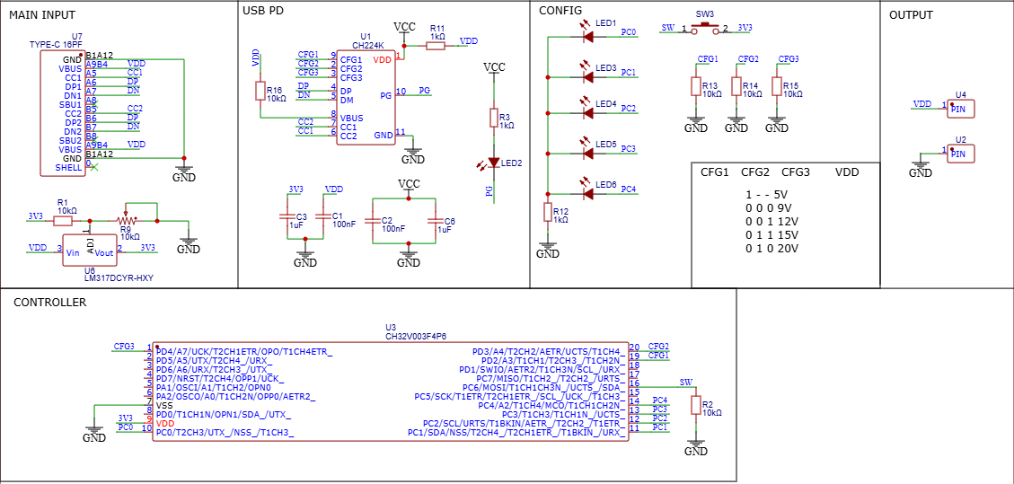
Schematic — CH224K CFG lines, LM317 supply, LEDs
Firmware
The firmware is minimal C written in WCH's MounRiver Studio. Three lookup arrays map mode index (0–4) to CFG pin states and the active LED pin. On each button press, the code reads the GPIO, applies a 20ms debounce delay, increments the mode index (wrapping at 4), then calls applyMode(). That function clears all LEDs, drives the three CFG pins from the lookup tables, and lights the correct LED. Boot defaults to 5V — the safest starting voltage since every PD charger supports it.
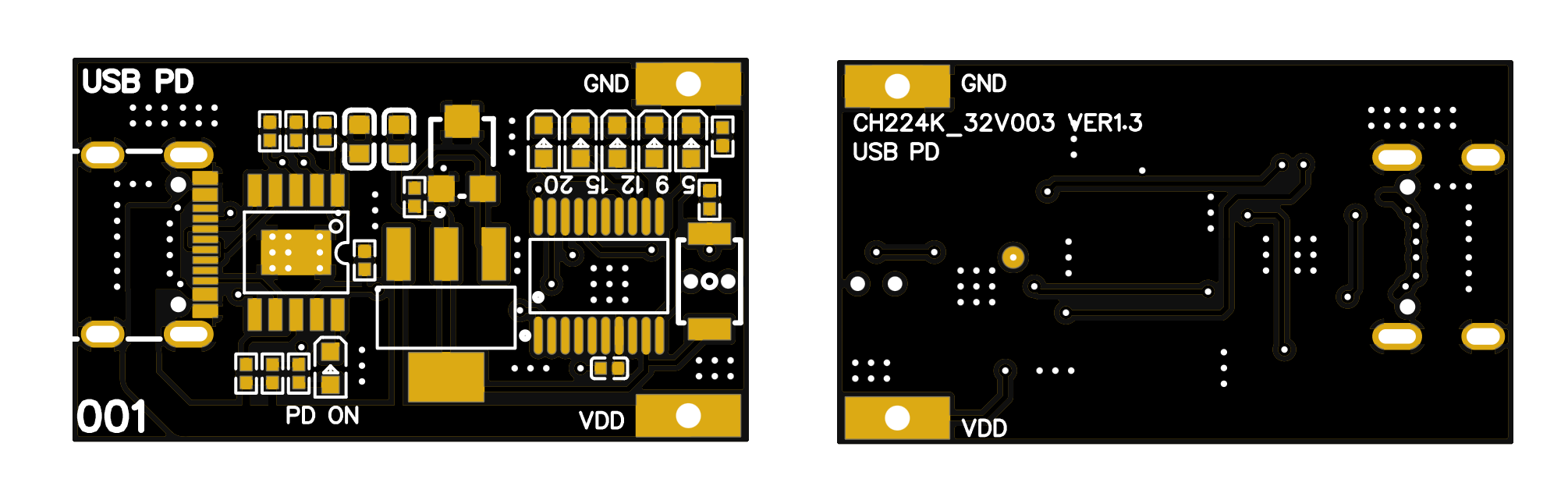
Compact 2-layer PCB from JLCPCB — USB-C left, LEDs and button right
Testing
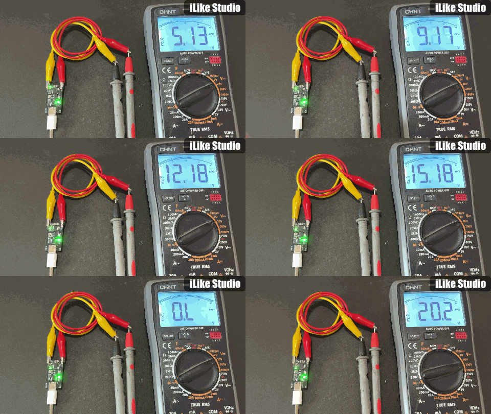
I brought up the board with a USB meter in series for overcurrent protection. It worked first try. After confirming idle current, I switched to the charger directly and measured all five voltages with a multimeter, each one correct on button press.
Sign In Or Register Comment after
No comments yet. Be the first to comment!