


A Simple RC Filter Can Clean Up More Than You Think
 View
View
Not every signal produced by a sensor or electronic circuit is perfectly clean. Electrical noise from switching power supplies, motors, relays, and nearby digital circuits can introduce unwanted fluctuations that affect measurement accuracy. In some cases, the signal changes so rapidly that a microcontroller struggles to distinguish useful information from high-frequency noise.
One of the simplest ways to reduce unwanted noise is by using an RC filter. Consisting of only a resistor and a capacitor, this circuit can significantly improve signal quality without requiring complex hardware or software.
Although an RC filter is one of the first circuits taught in electronics, understanding where to place it—and when to use it—can make a noticeable difference in real-world designs.
How an RC Filter Works
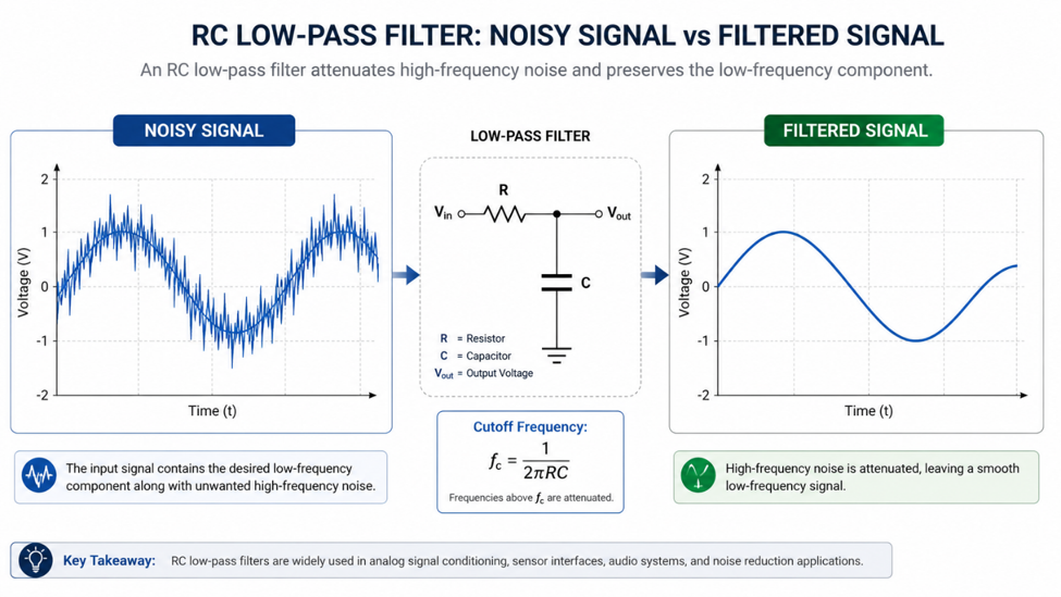
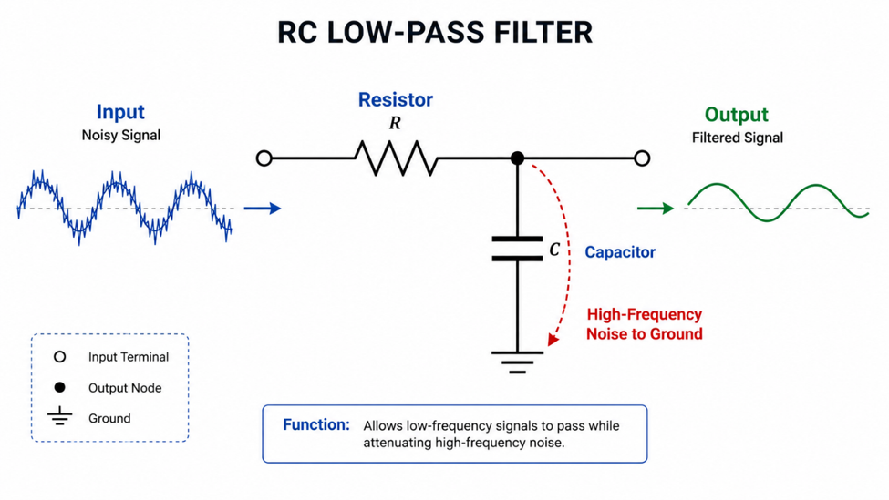
An RC low-pass filter consists of a resistor connected in series with the signal path and a capacitor connected from the signal line to ground.
At low frequencies, the capacitor has very high impedance, allowing the desired signal to pass with little attenuation. As the frequency increases, the capacitor's impedance decreases, diverting unwanted high-frequency noise to ground before it reaches the next stage of the circuit.
By selecting appropriate resistor and capacitor values, engineers can control the filter's cutoff frequency to match the application's requirements.
Common Applications
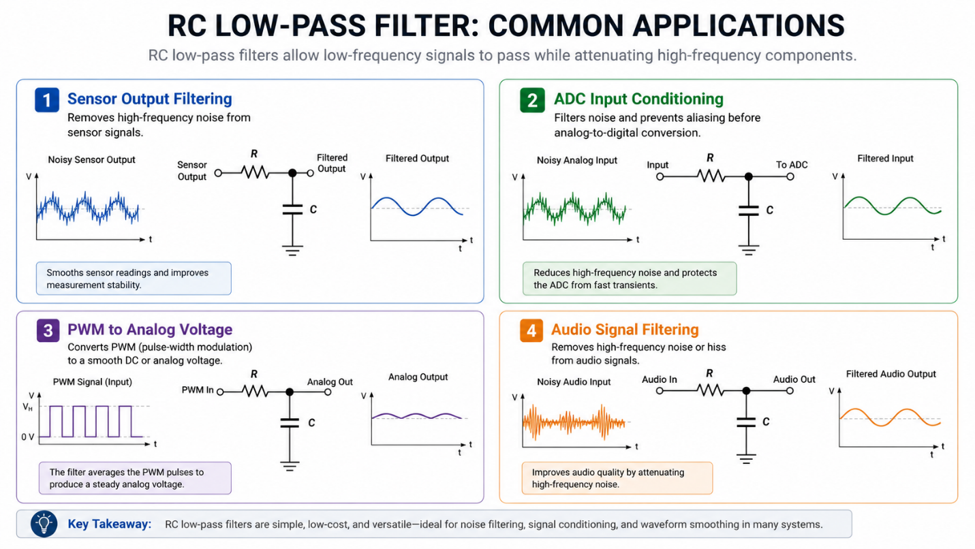
RC filters appear in many electronic systems because they are inexpensive, easy to design, and highly effective.
Typical applications include filtering sensor outputs before an ADC, smoothing PWM signals to create an analog voltage, reducing switch noise, filtering audio signals, and suppressing noise on communication lines where appropriate.
Although RC filters improve signal quality, choosing an excessively low cutoff frequency may slow the circuit's response. Finding the right balance between filtering and response time is an important part of the design process.
Recommended Components
The performance of an RC filter depends on selecting resistor and capacitor values that match the desired cutoff frequency.
Some commonly used components include:
| Component | Typical Value | Common Applications |
|---|---|---|
| Resistor | 1 kΩ | General analog filtering |
| Resistor | 10 kΩ | Sensor and ADC inputs |
| Ceramic Capacitor | 100 nF | General-purpose noise filtering |
| Ceramic Capacitor | 1 µF | Lower cutoff frequency applications |
Always calculate the required cutoff frequency before selecting component values rather than relying on standard values alone.
An RC filter is one of the simplest circuits in electronics, yet it plays an important role in improving signal quality. By understanding how resistor and capacitor values influence the cutoff frequency, designers can build measurement systems that are more stable, more accurate, and less susceptible to electrical noise.
#AnalogAndSignal# #RCFilter# #LowPassFilter# #SignalConditioning# #Electronics# #EmbeddedSystems#
 #AnalogAndSignal#
#RCFilter#
#LowPassFilter#
#SignalConditioning#
#Electronics#
#EmbeddedSystems#
#AnalogAndSignal#
#RCFilter#
#LowPassFilter#
#SignalConditioning#
#Electronics#
#EmbeddedSystems#
Sign In Or Register Comment after
No comments yet. Be the first to comment!