


Not Every Capacitor Belongs Next to the Power Input
 View
View
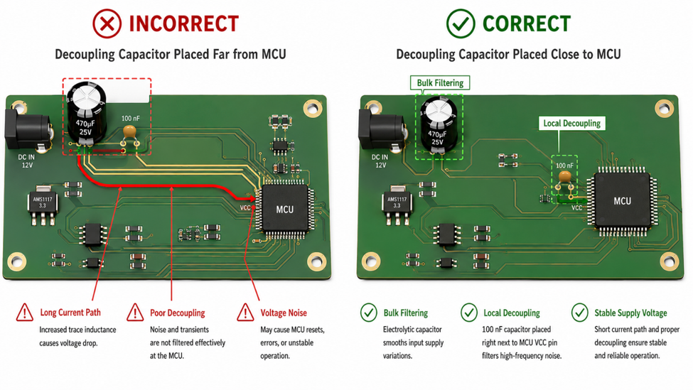
Capacitors are among the most common components in electronic circuits, yet their placement is just as important as their value. Many beginners focus on selecting the correct capacitance while the exact location on the PCB makes little difference. Moving a capacitor only a few centimeters away from where it is needed can significantly reduce its effectiveness.
This is especially true for power supply filtering. Different capacitors serve different purposes, and understanding where each one should be placed helps improve power stability, reduce noise, and prevent unexpected system behavior.
Rather than placing every capacitor near the power connector, good designs distribute capacitors according to the electrical demands of the circuit.
Understanding Their Different Roles
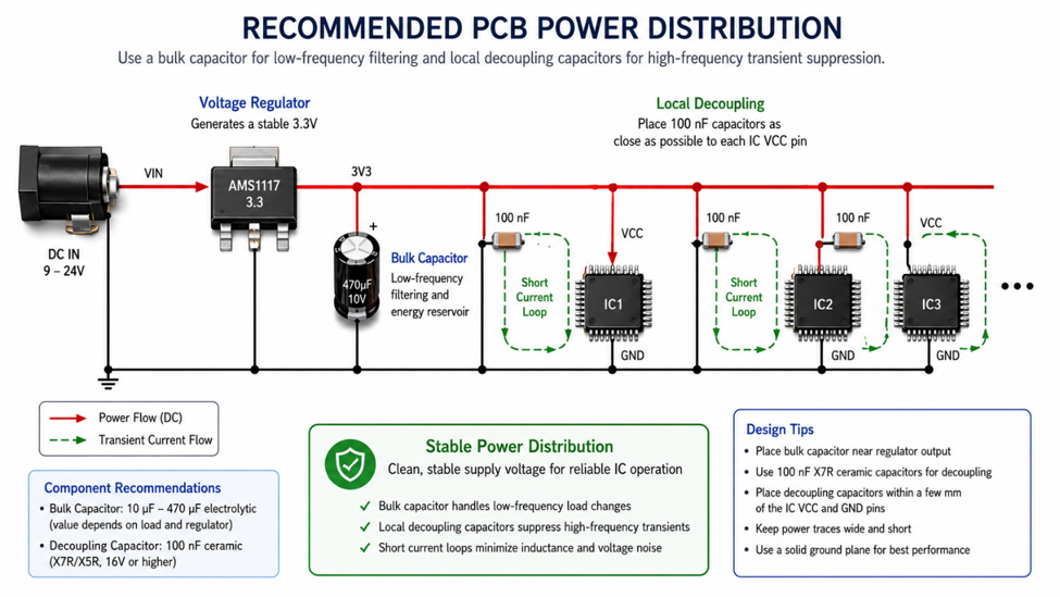
A bulk capacitor, typically an electrolytic or polymer capacitor, acts as an energy reservoir. It helps smooth low-frequency voltage ripple and supplies current during larger load changes. For this reason, it is usually placed close to the power connector or voltage regulator.
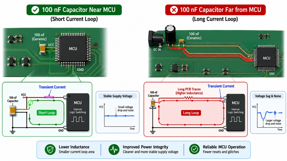
A decoupling capacitor serves a different purpose. Small ceramic capacitors, such as 100 nF, respond much faster to rapid current demands generated by microcontrollers, digital ICs, and communication devices. They should be positioned as close as possible to each power pin to minimize trace inductance.
Although both improve power quality, they work together rather than replacing one another.
Engineering Note
A 100 nF capacitor located 30 mm away from a microcontroller is often far less effective than one placed only a few millimeters from the VCC pin. At high frequencies, trace inductance can become more significant than the capacitor value itself.
Practical Design Tips
When reviewing a PCB layout, don't simply count the number of capacitors. Instead, verify that each capacitor is positioned according to its function.
A practical rule is:
- Place bulk capacitors near the power entry or voltage regulator.
- Place 100 nF ceramic capacitors immediately beside every MCU or digital IC power pin.
- Use wider power traces and a continuous ground plane to reduce impedance.
- Keep the connection between the capacitor and the IC as short as possible.
These simple placement practices often improve power integrity without changing the circuit schematic.
Recommended Components
The following capacitors are commonly used together in embedded and digital power systems.
| Component | Typical Value | Typical Applications |
|---|---|---|
| Murata GRM188R71H104KA93 | 100 nF Ceramic | MCU and digital IC decoupling |
| Samsung CL10B104KB8NNNC | 100 nF Ceramic | General-purpose bypass capacitor |
| Panasonic FR Series | 47–220 µF Electrolytic | Power input filtering |
| Nichicon UHE Series | 100–470 µF Electrolytic | Bulk energy storage |
Always refer to the microcontroller or IC datasheet, as many manufacturers specify the recommended capacitor values and placement guidelines for optimal performance.
Choosing the correct capacitor value is only part of good circuit design. Proper placement determines how effectively that capacitor can perform its job. By placing bulk capacitors where power enters the circuit and locating decoupling capacitors directly beside each IC, engineers can significantly improve power stability, reduce electrical noise, and build more reliable electronic systems.
#PowerAndEnergy# #DecouplingCapacitor# #PowerIntegrity# #PCBDesign# #EmbeddedSystems# #Electronics#
 #PowerAndEnergy#
#DecouplingCapacitor#
#PowerIntegrity#
#PCBDesign#
#EmbeddedSystems#
#Electronics#
#PowerAndEnergy#
#DecouplingCapacitor#
#PowerIntegrity#
#PCBDesign#
#EmbeddedSystems#
#Electronics#
Sign In Or Register Comment after
No comments yet. Be the first to comment!