


Why Sensor Signals Need Signal Conditioning Before the ADC
 View
View
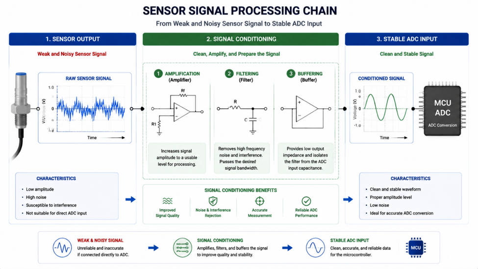
Many sensors can measure real-world parameters such as temperature, pressure, force, and light intensity. However, the signal produced by a sensor is not always ready to be connected directly to a microcontroller ADC.
A sensor output may be too small, too noisy, too slow, or outside the ADC input range. Connecting it directly can result in inaccurate measurements or unstable readings.
This is why many electronic systems use signal conditioning circuits before the ADC stage. These circuits prepare the sensor output so the microcontroller can measure it more accurately and reliably.
Signal conditioning is commonly used in industrial measurement systems, medical devices, IoT sensors, and automation equipment.
Why Raw Sensor Signals Are Difficult to Measure
Different sensors produce different types of output signals.
Some sensors generate very small voltages, such as strain gauges and thermocouples. Others may produce signals with electrical noise from the environment or require impedance matching before measurement.
Common problems include:
- Signal amplitude is too low.
- High-frequency noise interference.
- Sensor output impedance too high.
- Voltage range not matching the ADC input.
Without proper conditioning, the ADC may not utilize its available resolution effectively.
Common Signal Conditioning Techniques
Amplification
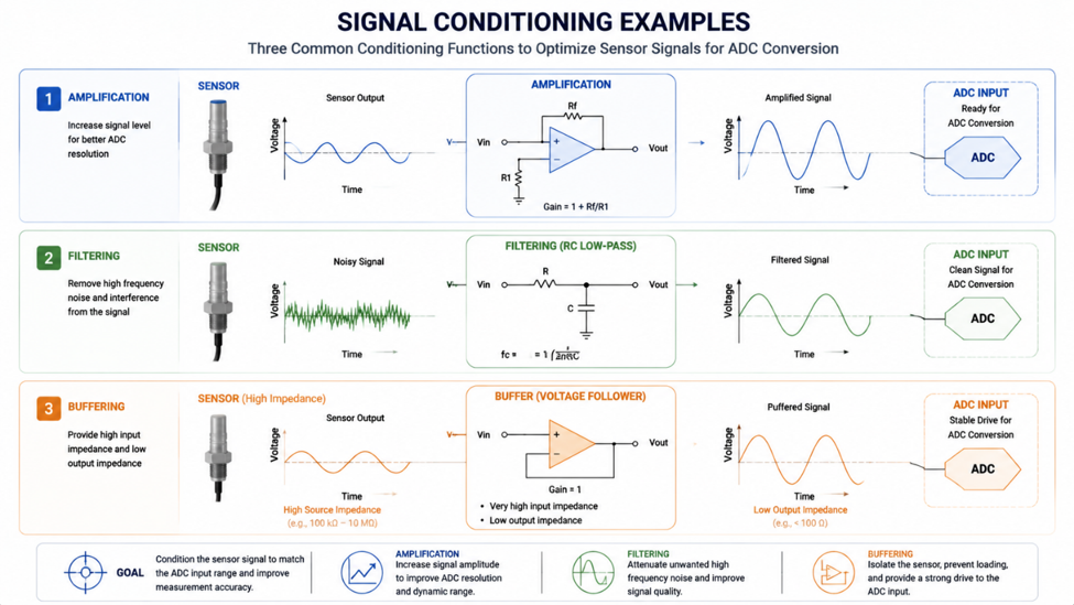
Small sensor signals often need amplification before entering the ADC.
For example, a load cell may produce only a few millivolts, requiring an instrumentation amplifier to increase the signal level.
Filtering
Filters remove unwanted noise from the measurement signal.
An RC low-pass filter is commonly used to reduce high-frequency interference before sampling.
Buffering
A voltage buffer prevents the sensor from being loaded by the ADC input.
This is useful for sensors with high output impedance.
Example Application: Load Cell Measurement
A load cell is a good example of why signal conditioning is required.
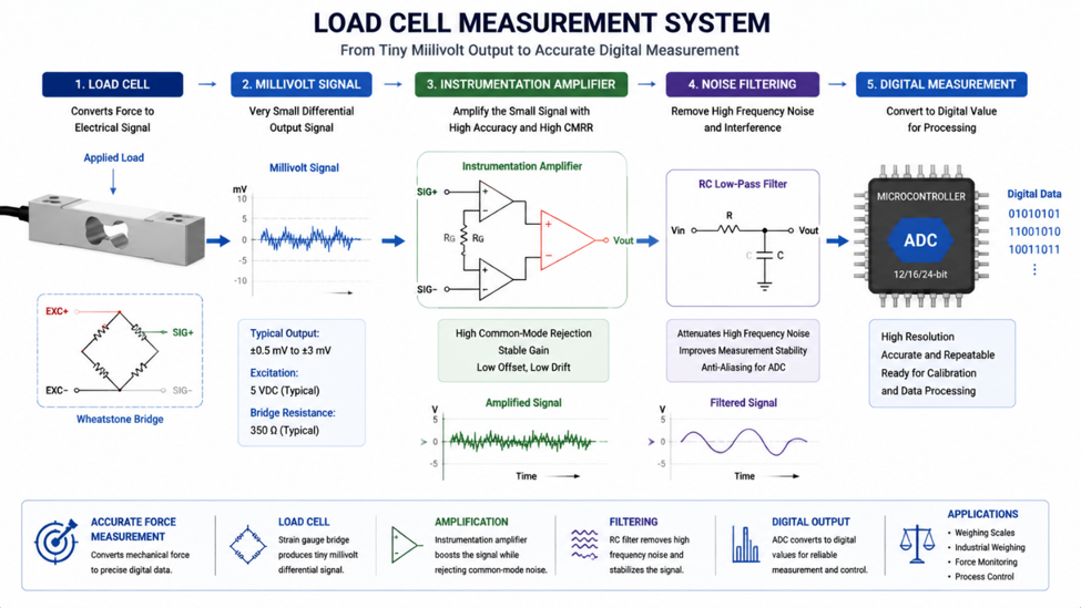
The output voltage from a strain gauge load cell is extremely small and usually cannot be measured accurately by a microcontroller ADC directly.
A typical system uses:
- Wheatstone bridge sensor
- Instrumentation amplifier
- Low-pass filter
- ADC converter
This combination increases signal accuracy and improves resistance against electrical noise.
Recommended Components
| Device | Type | Typical Application |
|---|---|---|
| INA333 | Instrumentation Amplifier | Sensor measurement |
| OPA320 | Precision Op-Amp | Analog buffering |
| MCP6002 | Low Power Op-Amp | Battery sensor systems |
| ADS1115 | 16-bit ADC | High-resolution measurement |
Engineering Tip
A high-resolution ADC cannot recover information that was lost because of a noisy or poorly conditioned signal. Good measurement starts before the ADC stage.
Signal conditioning is an essential part of reliable measurement systems. Sensors rarely produce perfect signals, and the role of analog circuitry is to prepare these signals before digital conversion.
By applying amplification, filtering, and buffering techniques, engineers can improve accuracy, reduce noise, and create measurement systems that perform reliably in real-world conditions.
#AnalogAndSignal# #SignalConditioning# #ADC# #Sensors# #EmbeddedSystems# #Electronics#
 #AnalogAndSignal#
#SignalConditioning#
#ADC#
#Sensors#
#EmbeddedSystems#
#Electronics#
#AnalogAndSignal#
#SignalConditioning#
#ADC#
#Sensors#
#EmbeddedSystems#
#Electronics#
Sign In Or Register Comment after
No comments yet. Be the first to comment!