


Why Your Op-Amp Circuit Becomes Unstable
 View
View
Operational amplifiers (op-amps) are one of the most widely used analog components. They appear in sensor interfaces, audio circuits, filters, signal amplifiers, and measurement systems.
However, many engineers experience unexpected problems when using op-amps: oscillation, unstable output, unexpected noise, or incorrect voltage levels.
The schematic may look correct, but the circuit still does not behave as expected.
In many cases, the problem is not the op-amp itself. The issue comes from incorrect feedback design, insufficient power decoupling, unsuitable component selection, or ignoring the limitations described in the datasheet.
Understanding op-amp stability is essential for building reliable analog circuits.
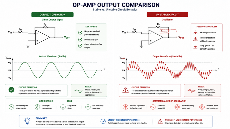
Common Causes of Op-Amp Instability
Several design issues can cause an op-amp circuit to behave unpredictably.
Incorrect Feedback Design
The feedback network determines how the op-amp behaves. Incorrect resistor values or unexpected parasitic effects can reduce stability and create oscillation.
Poor Power Supply Decoupling
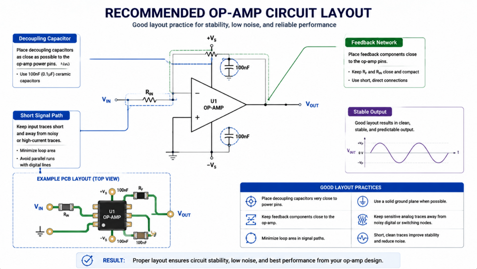
Op-amps respond quickly to changes in their input signal. Without proper bypass capacitors near the power pins, supply noise can directly affect the output.
Driving Capacitive Loads
Some op-amps become unstable when directly driving large capacitors or long cables because the additional capacitance changes the feedback behavior.
Choosing the Wrong Op-Amp
Different op-amps have different characteristics:
- Gain bandwidth.
- Slew rate.
- Input offset voltage.
- Output drive capability.
Selecting an op-amp based only on voltage rating is often not enough.
Engineering Note
An op-amp with very high bandwidth is not always better. Higher speed often requires more careful PCB layout, compensation, and stability analysis.
Practical Design Checklist
Before testing an op-amp circuit, review:
✓ Is the feedback network connected correctly?
✓ Are bypass capacitors placed close to the supply pins?
✓ Is the selected op-amp suitable for the required gain?
✓ Can the output drive the connected load?
✓ Is the input signal within the allowed common-mode range?
These checks can prevent many hours of troubleshooting.
Recommended Devices
| Device | Type | Typical Application |
|---|---|---|
| OPA320 | Precision Rail-to-Rail Op-Amp | Sensor interfaces |
| MCP6002 | Low Power Op-Amp | Battery systems |
| TLV9062 | General Purpose Op-Amp | Embedded analog circuits |
| OPA365 | High Speed Op-Amp | Fast signal processing |
Op-amps are simple in concept but require careful design in practice. A circuit that works perfectly on paper can become unstable due to feedback issues, power supply noise, PCB layout, or component limitations.
By selecting the correct op-amp, designing the feedback network properly, and following good layout practices, engineers can build analog circuits that are stable, accurate, and reliable.
#AnalogAndSignal# #OpAmp# #AnalogCircuit# #SignalProcessing# #Electronics# #EmbeddedSystems#
 #AnalogAndSignal#
#OpAmp#
#AnalogCircuit#
#SignalProcessing#
#Electronics#
#EmbeddedSystems#
#AnalogAndSignal#
#OpAmp#
#AnalogCircuit#
#SignalProcessing#
#Electronics#
#EmbeddedSystems#
Sign In Or Register Comment after
No comments yet. Be the first to comment!