


Logic Analyzer vs Oscilloscope: Which Tool Should You Use?
 View
View
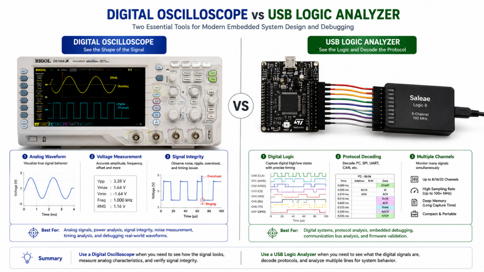
When debugging an electronic circuit, one of the first questions engineers face is whether they need a logic analyzer or an oscilloscope. Both instruments help visualize electrical signals, but they are designed for different purposes.
An oscilloscope shows the actual analog waveform, allowing engineers to measure voltage, noise, rise time, and signal quality. A logic analyzer focuses on digital logic states, making it easier to decode communication protocols and monitor multiple digital channels simultaneously.
Understanding the strengths of each instrument helps reduce debugging time and improves measurement accuracy.
When to Use an Oscilloscope
An oscilloscope measures how voltage changes over time.
It is the preferred tool when you need to:
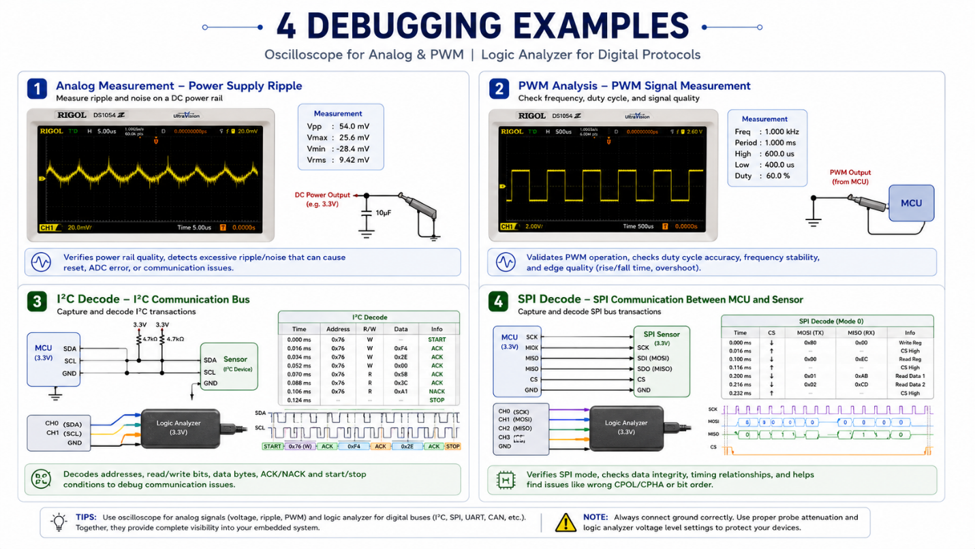
- Verify power supply ripple.
- Measure PWM duty cycle.
- Observe analog sensor outputs.
- Check signal overshoot or ringing.
- Analyze clock waveform quality.
Because it captures the complete waveform, an oscilloscope provides information that cannot be obtained from digital logic measurements alone.
When to Use a Logic Analyzer
A logic analyzer samples digital HIGH and LOW states across many channels simultaneously.
It is particularly useful for debugging communication interfaces such as:
- I²C
- SPI
- UART
- CAN
- GPIO timing
Many logic analyzers also decode communication protocols automatically, allowing engineers to inspect transmitted data without manually interpreting digital pulses.
Quick Comparison
| Feature | Oscilloscope | Logic Analyzer |
|---|---|---|
| Signal Type | Analog & Digital | Digital Only |
| Voltage Measurement | ✔ | ✖ |
| Protocol Decoding | Limited | Excellent |
| Number of Channels | Usually 2–4 | Often 8–16 or more |
| Best For | Signal Quality | Digital Communication |
Recommended Equipment
| Device | Type | Typical Application |
|---|---|---|
| Rigol DS1054Z | Digital Oscilloscope | General electronics debugging |
| Siglent SDS1104X-E | Digital Oscilloscope | Embedded and analog design |
| Saleae Logic 8 | Logic Analyzer | Protocol decoding and embedded debugging |
| DreamSourceLab DSLogic U3Pro16 | Logic Analyzer | Multi-channel digital analysis |
Engineering Tip
If you are debugging SPI or I²C data, start with a logic analyzer. If you suspect signal quality issues such as ringing, noise, or incorrect voltage levels, switch to an oscilloscope. In many projects, both tools complement each other rather than replace one another.
Oscilloscopes and logic analyzers are designed for different measurement tasks. An oscilloscope reveals the electrical characteristics of a signal, while a logic analyzer focuses on digital communication and timing.
Choosing the right instrument for the job allows engineers to identify problems more quickly and gain a deeper understanding of how their circuits behave.
#TestAndMeasurement# #Oscilloscope# #LogicAnalyzer# #EmbeddedSystems# #Debugging# #Electronics#
 #TestAndMeasurement#
#Oscilloscope#
#LogicAnalyzer#
#EmbeddedSystems#
#Debugging#
#Electronics#
#TestAndMeasurement#
#Oscilloscope#
#LogicAnalyzer#
#EmbeddedSystems#
#Debugging#
#Electronics#
Sign In Or Register Comment after
No comments yet. Be the first to comment!