


Why Your Circuit Works on a Breadboard but Fails on a PCB
 View
View
One of the most frustrating experiences in electronics development is seeing a circuit work perfectly on a breadboard but fail after being transferred to a printed circuit board (PCB). The schematic hasn't changed, the components are the same, and the firmware is identical—yet the finished hardware behaves differently.
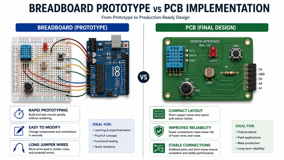
This situation is surprisingly common. A breadboard is an excellent tool for rapid prototyping, but it does not accurately represent the electrical characteristics of a real PCB. Wire length, contact resistance, parasitic capacitance, and grounding all become more important as circuit complexity increases.
Understanding these differences helps engineers avoid unpleasant surprises during the transition from prototype to production.
Why the Results Can Be Different
Breadboards introduce electrical characteristics that are rarely visible in simple projects.
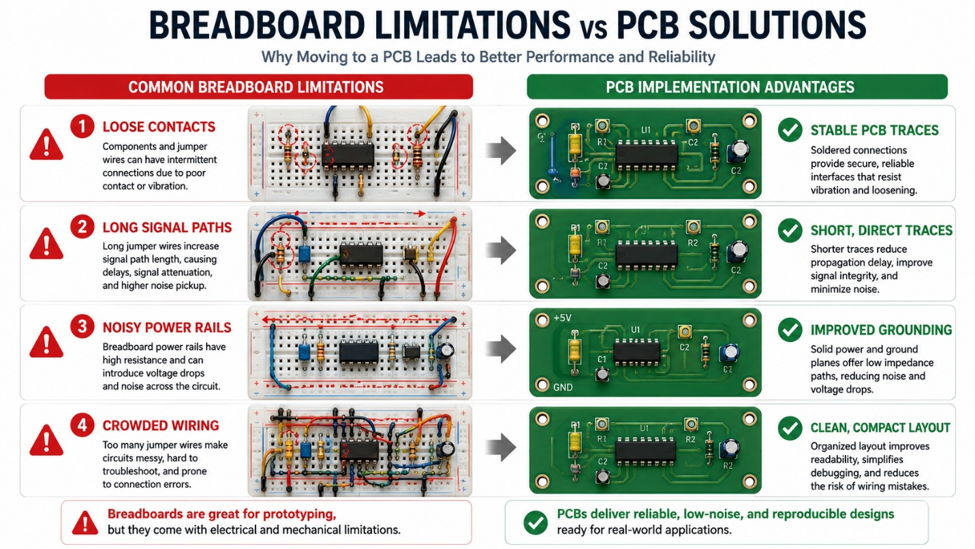
Long jumper wires increase inductance and can pick up electrical noise. Contact resistance varies between connection points, and the shared power rails may create unwanted voltage drops when supplying higher currents.
On a PCB, traces are shorter, connections are soldered, and the ground system is much more predictable. These improvements often eliminate intermittent problems that appear during breadboard testing.
Best Practices Before Building a PCB
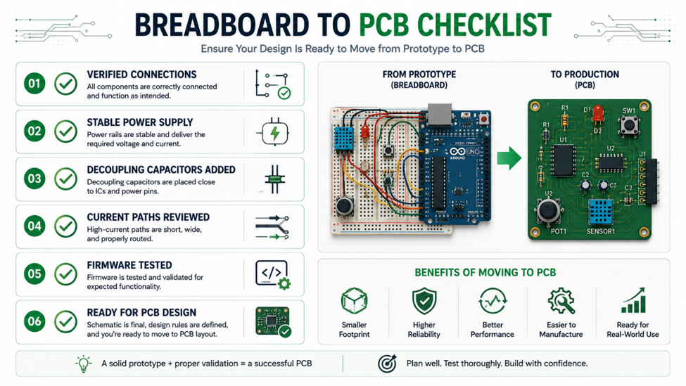
Before converting a prototype into a PCB design, review the following points:
- Verify every connection on the breadboard.
- Measure supply voltage under load.
- Keep high-current paths as short as possible.
- Add proper decoupling capacitors near IC power pins.
- Test the circuit for an extended period before finalizing the design.
These simple checks reduce the likelihood of discovering problems only after the PCB has been manufactured.
Engineering Note
A breadboard proves that a concept can work. A well-designed PCB proves that it can work reliably. Successful products require both stages.
Recommended Tools
| Tool | Purpose | Typical Application |
|---|---|---|
| Solderless Breadboard | Rapid prototyping | Circuit testing |
| Jumper Wire Kit | Temporary wiring | Breadboard connections |
| Digital Multimeter | Electrical verification | Voltage and continuity checks |
| Logic Analyzer | Digital debugging | I²C, SPI, UART troubleshooting |
Breadboards are invaluable for experimenting with new ideas, but they should not be expected to behave exactly like a finished PCB. Understanding the electrical differences between temporary prototypes and permanent circuit boards allows engineers to design more reliable hardware and move into production with greater confidence.
#MakersAndEducationSpaces# #Breadboard# #PCBDesign# #ElectronicsLearning# #Prototype# #Electronics#
 #MakersAndEducationSpaces#
#Breadboard#
#PCBDesign#
#ElectronicsLearning#
#Prototype#
#Electronics#
#MakersAndEducationSpaces#
#Breadboard#
#PCBDesign#
#ElectronicsLearning#
#Prototype#
#Electronics#
Sign In Or Register Comment after
No comments yet. Be the first to comment!