logo
  • JLCPCB - PCB/PCBA
  • JLC3DP - 3D Printing
  • JLCCNC - CNC Machining
  • JLCMC - Mechatronic Parts
more
All posts
Electronic Community
Electronic Tips & Projects
Design & Manufacturing
Embedded Systems2
Microcontrollers
FPGA & Programmable Logic
Analog & Signal
Power & Engery
RF & Wireless
Sensors & Actuators
Wireless & IOT
Automation & Control
Test & Measurement
Equipment & Tools & Resources
Makers & Education Spaces
JLCDMP
JLCDMP 3D Viewer
Mechanical Community
Mechanical Tips & Projects
Mechanical Design
CAD & 3D Modeling
CNC Machining & Milling
Mechanical Components & Sourcing
Manufacturing & Machines
Mechatronic Systems
Industry Applications
Workshop Tools & Metrology
tesst007
OSHWLab
Activities
Projects
Others
JLCPCB
PCB
FPC
PCBA
SMT Stencil
Layout
Flexible Heater
SMT Components
JLC3DP
SLA (Resin)
MJF (Nylon)
SLM (Metal)
FDM (Plastic)
SLS (Nylon)
WJP (Resin)
BJ (Metal)
JLCCNC
CNC Machining
Sheet Metal Fabrication
JLCMC
Mechatronic Components
Custom Parts
JLCONE
Desktop App
Mobile App
EasyEDA
Circuit Design
Feature Requests
Bug Reports
API & Extension
Others
JLCCAN
JLCCAN Help & Tips
SOLIDWORKS Automation
Projects & Showcase
LCSC Cable
Technical Discussion
Showcase
Help & Support
LCSC Panel
Technical Discussion
Showcase
Help & Support
asdasdasd
Terms Privacy Cookies
© 2026 JLCHUB.COM All Rights Reserved.

Follow
0
Posts
0
Comments
0
Followers
SheetMetal
Official
2026-01-28 07:30:42 151 Views
Sheet Metal vs CNC Machining: How Do You Decide?

A common question in real projects is:
Should this part be sheet metal or CNC machined?

The answer is not about “which is better” but which is more suitable.

🔸 Sheet metal works best when:

  • Wall thickness is uniform
  • Parts are enclosure-like or structural
  • Quantities are medium to large
  • Cost efficiency matters

🔸 CNC machining works best when:

  • Complex 3D geometry is required
  • Tight tolerances are critical
  • Parts are thick or solid
  • Quantities are small or prototype-focused

📌 In real projects, the best solution is often:
Sheet metal + CNC parts combined for optimal cost and performance.

💬 Discussion:
Have you ever chosen the wrong process and later regretted it?
What would you do differently next time?

#sheetmetal# #JLCCNC#

Sheet Metal Fabrication

Follow
0
Posts
0
Comments
0
Followers
SheetMetal
Official
2026-01-28 07:28:11 Edited 154 Views
From Drawing to Reality: How a Sheet Metal Part Is Made

Many designers and makers only see the final sheet metal part, not the full manufacturing process behind it.

A typical sheet metal workflow looks like this:

1️⃣ Laser cutting – defines shape and hole accuracy

2️⃣ Bending – the most critical forming step

3️⃣ Welding or riveting (if needed) – creates assemblies

4️⃣ Surface finishing – powder coating, anodizing, brushing, etc

📌 Why does this matter?

Understanding the process helps you:

  • Reduce unnecessary cost
  • Improve manufacturability
  • Shorten production lead time

💬 Discussion:

Which step of sheet metal fabrication concerns you the most—precision, bending accuracy, or surface finish?

#sheetmetal# #JLCCNC#

Sheet Metal Fabrication

Follow
0
Posts
0
Comments
0
Followers
SheetMetal
Official
2026-01-28 07:08:04 128 Views
Aluminum, Steel Alloy, or Stainless Steel? How to Choose Sheet Metal Materials

Material selection in sheet metal directly affects:

  • Cost
  • Strength
  • Appearance
  • Lead time

Simply writing "Material: Aluminum" in a drawing is often not enough.

🔹 Common sheet metal materials

Cold-rolled steel/ Galvanized steel sheet

  • Low cost
  • Good strength
  • Ideal for powder coating
  • Requires surface treatment to prevent rust

Stainless steel (304 / 201)

  • Excellent corrosion resistance
  • Premium appearance
  • Higher cost and forming difficulty

Aluminum alloys (5052)

  • Lightweight
  • 5052 offers excellent bending performance
  • Suitable for anodizing

📌 Typical use cases:

Industrial enclosures: SPCC + powder coating

Lightweight or consumer products: aluminum

Outdoor or corrosive environments: stainless steel

For more details on materials cost, you can refer to How to Choose the Materials in Sheet Metal Fabrication

💬 Discussion:
When choosing sheet metal materials, what matters most to you—cost, weight, strength, or appearance?

#sheetmetal# #JLCCNC#

Sheet Metal Fabrication

Follow
0
Posts
0
Comments
0
Followers
SheetMetal
Official
2026-01-28 07:01:35 109 Views
90% of Sheet Metal Problems Start in the Design Stage

From real production experience, most sheet metal issues are not caused by manufacturing, but by design decisions made early on.

Here are some common design mistakes we see repeatedly:

1️⃣ Zero bend radius

In real fabrication, a bend radius can never be zero.
Minimum bend radius depends on material type and thickness, and ignoring this often causes cracking or deformation.

2️⃣ Holes too close to bend lines

Holes or slots placed too close to a bend line may lead to:

  • Distortion
  • Cracking
  • Unstable dimensions

3️⃣ No consideration for assembly sequence

A part may look fine in CAD, but once bent:

  • Tools cannot reach
  • Parts cannot be assembled
  • Welding becomes impossible

📌 Design tip:
When designing sheet metal parts, always ask:
👉 “How will this part actually be manufactured step by step?”

💬 Discussion:
What is the biggest sheet metal design mistake you've made or seen?
Bend issues, tolerances, or assembly problems?

#sheetmetal# #JLCCNC#

Sheet Metal Fabrication

Follow
0
Posts
0
Comments
0
Followers
User Avatar
fixit9660
2026-01-27 12:00:46 Edited 86 Views
Experienced electronic engineer but can't find components

I'm an experienced electronic engineer trying to use EasyEDA for the first time. I'm only trying to connect two components on a small pcb. My problem is that the components are probably rare and complex, and so might not even exist, even though they are old.

I'm looking for a Female DIN 41612 64pin 2x32pin Type C Rows A & C right angle connector, and a  2.54mm Pitch 2x32 Pin 64 Pin Male Header FD IDC Cable Transition Connector.

Can anyone tell me if they even exist please?

Thank you.

#PCB#
Circuit Design

Follow
0
Posts
0
Comments
0
Followers
Johan_Petrovic
2026-01-27 05:54:34 121 Views
The flexible heaters from JLCPCB such a low price!

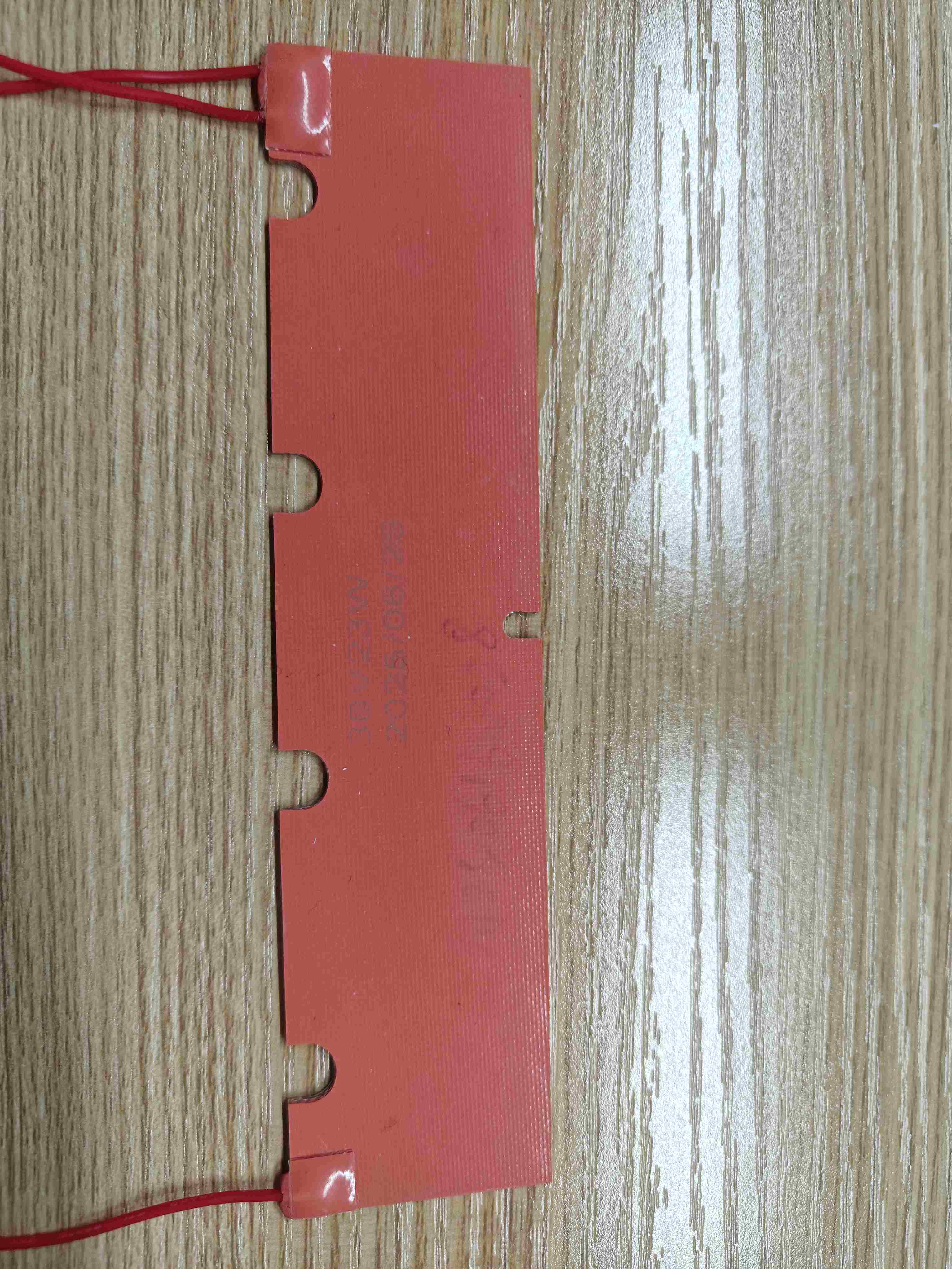
I bought a silicone heater just like this on JLCPCB for less than five US dollars. It’s insanely cheap, and it’s more than enough to make a pair of hand warmers.

8704367956122517504

Flexible Heater

Follow
0
Posts
0
Comments
0
Followers
User Avatar
yusufshn3147
2026-01-27 02:43:49 Edited 100 Views
Underwater Vehıcle

I’m starting an open-source underwater vehicle project on OSHWLab.

My goal is to design a practical, modular, and buildable underwater platform (hardware + firmware), and share everything publicly: schematics, PCB files, BOM, 3D parts, wiring diagrams, and test results.

What I’ll share here

  • Step-by-step design decisions (what works / what doesn’t)

  • PCB revisions and hardware updates

  • Firmware progress (sensors, motor control, communication, etc.)

  • Assembly notes, waterproofing ideas, and real-world testing videos/photos

  • Problems I hit and how I solve them (so others can learn faster)

Why open-source?

I want this project to be easy for makers, student teams, and robotics builders to reproduce, modify, and improve.

✅ Follow this project to stay updated — I’ll post regular progress logs and new releases here.

#Project#
Projects

Follow
0
Posts
0
Comments
0
Followers
User Avatar
prumpiseth6
2026-01-26 05:44:51 Edited 63 Views
DC-AC220VAC

DC/AC INVERTER

#Schematic#
Circuit Design

Follow
0
Posts
0
Comments
0
Followers
JLCPCBStencil
Official
2026-01-26 02:38:25 135 Views
Bottom Side Stencil: Don’t forget the underside

A Bottom Side Stencil follows the bottom side data of your Gerber file.

Use this if your PCB has components on the bottom side and you want precise paste deposition.

💬 Have you ever tried printing the bottom side first, or do you usually start with the top?

SMT Stencil

Follow
0
Posts
0
Comments
0
Followers
JLCPCBStencil
Official
2026-01-26 02:36:51 131 Views
Top + Bottom on Separate Stencils——Two stencils

This is the standard method for double-sided PCB assembly:

One stencil for the top side

One stencil for the bottom side

It gives you full flexibility, easier handling, and usually better printing consistency.

💬 Which method do you prefer for double-sided boards: single stencil or separate stencils? Why?

SMT Stencil

Follow
0
Posts
0
Comments
0
Followers
JLCPCBStencil
Official
2026-01-26 02:35:24 191 Views
Top Bottom on a Stencil—One sheet, double data

his option lets you create one stencil that contains both top and bottom side patterns from your Gerber files.

It can be convenient for some prototyping or small-size PCBs, but make sure your assembly method supports it.

💬 Question: Have you ever used a single stencil for both sides? How did it go?

SMT Stencil

Follow
0
Posts
0
Comments
0
Followers
User Avatar
987654aB185K
2026-01-26 02:31:58 153 Views
Bottom Side Stencil: Don’t forget the underside

A Bottom Side Stencil follows the bottom side data of your Gerber file.

Use this if your PCB has components on the bottom side and you want precise paste deposition.

💬 Have you ever tried printing the bottom side first, or do you usually start with the top?

SMT Stencil

Follow
0
Posts
0
Comments
0
Followers
User Avatar
richardpope
2026-01-25 05:29:10 Edited 59 Views
PDF Manuals

Are EasyEDA Manuals available??

Thanks,

rich!

#Schematic#
Circuit Design

Follow
0
Posts
0
Comments
0
Followers
User Avatar
absakgaming
2026-01-24 07:14:23 Edited 61 Views
please fix the login-out issue on the desktop app for windows 11

please, it's frustrating to use a software that keeps on login you out every other week, can't you figure it out by now ?


please, i'm begging you it's really frustrating...

#Others#
Others

Follow
0
Posts
0
Comments
0
Followers
User Avatar
JLCPCB Flex Heater
Official
2026-01-24 01:33:15 108 Views
Why Choose Flexible Heaters? Key Advantages

Flexible heaters offer several benefits over traditional heating solutions:

✅ Conformability - adheres to curved, complex surfaces

✅ Thin profile - adds minimal thickness to your design

✅ Fast response - quick heat-up and cool-down times

✅ Energy efficient - heat is applied directly where needed

✅ Customizable - any shape, size, power density, voltage

✅ Durable - withstands vibration, bending, harsh environments.

Common applications include: anti-condensation, freeze protection, process heating, comfort warming, and temperature compensation in electronics. What applications are you considering?

8703215032700338176

8703215032910323712

Flexible Heater

Follow
0
Posts
0
Comments
0
Followers
User Avatar
heneelrajguru
2026-01-23 11:43:47 Edited 25 Views
Highlight the Ratlines when components are selected using Cross Probe.

Hi,

I am facing a small difficulty while routing my PCB in EasyEDA.

When I use Cross Probe, the related components from the Schematic get highlighted in the PCB Layout. This part is working perfectly and is very helpful.

But during routing, I want one more thing:
I want to see or highlight only the ratlines (airwires) that are connected to those highlighted components.

Right now, the only way I know is to manually check/uncheck nets in the Design Manager, which becomes slow and confusing when the design has many nets.

So my question is:
Is there any method or setting to automatically highlight only the ratlines related to the cross-probed components?
Something that filters the connections visually would make routing much easier.

Thanks in advance for the help!

#PCB#
Circuit Design

Follow
0
Posts
0
Comments
0
Followers
JLCPCB
Official
2026-01-23 10:22:33 171 Views
FREE Tools for FPC Design

FPC Gold Fingers PI Thickness Calculator

Designing for a ZIF connector? Don't risk a loose connection! This tool helps you calculate the exact combination of base copper, adhesive, and PI stiffeners to meet connector specs.

  • Best for: Ensuring your FPC fits perfectly into its socket.
  • Try it here:FPC Thickness Calculator
FPC

Follow
0
Posts
0
Comments
0
Followers
JLCPCB
Official
2026-01-23 10:14:07 128 Views
Show & Tell: What’s on Your Workbench This Month?

Every month is a new chance to innovate! Whether it's a simple LED blinker or a complex drone controller, we want to see what you're building.

Community Bonus: Did you know? From next month, every EasyEDA user gets $20 coupons every month upon file export.

  1. Finish your project.
  2. Export from EasyEDA.
  3. Claim your $10 PCB +$10 PCBA Coupon.
  4. Post a photo of your finished board here!

What are you ordering with your coupon? Share your project below!

FPC

Follow
0
Posts
0
Comments
0
Followers
JLCPCB
Official
2026-01-23 06:31:02 210 Views
Free Tool Inside - Impedance Calculator

How to Calculate PCB Impedance in Seconds!
Designing high-speed boards? Then you know that matching impedance is non-negotiable for signal integrity.
Instead of manual math, use the JLCPCB Impedance Calculator. Simply input your layer stackup and trace width to get instant results.

JLCPCB Impedance Calculator:

https://jlcpcb.com/pcb-impedance-calculator

PCB

Follow
0
Posts
0
Comments
0
Followers
JLCPCB
Official
2026-01-23 06:26:35 253 Views
How to Choose the Right PCB Thickness?

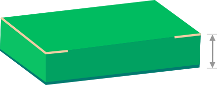
Choosing PCB thickness isn't just about aesthetics. If you're stuck between 1.0mm and 1.6mm, ask yourself these 4 questions:

  1. Mechanical Strength: Will it carry heavy transformers or heat sinks? (Go thicker >1.6mm)

  2. Housing Space: Is your enclosure ultra-slim? (Go thinner <0.8mm)

  3. Signal Type: High-power traces need thicker copper, which adds to the total board thickness.

  4. Cost & Lead Time: Standard thicknesses (like 1.6mm) are usually the fastest and cheapest to produce.

JLC Capability: Thickness for FR4 are: 0.4/0.6/0.8/1.0/1.2/1.6/2.0 mm (2.5 mm and above are for 12+ layer PCBs only)

Read the full breakdown on our blog: https://jlcpcb.com/blog/how-to-choose-the-thickness-of-pcb
8702926291610554368

PCB