Why Microcontrollers Reset When the Voltage Drops for a Moment

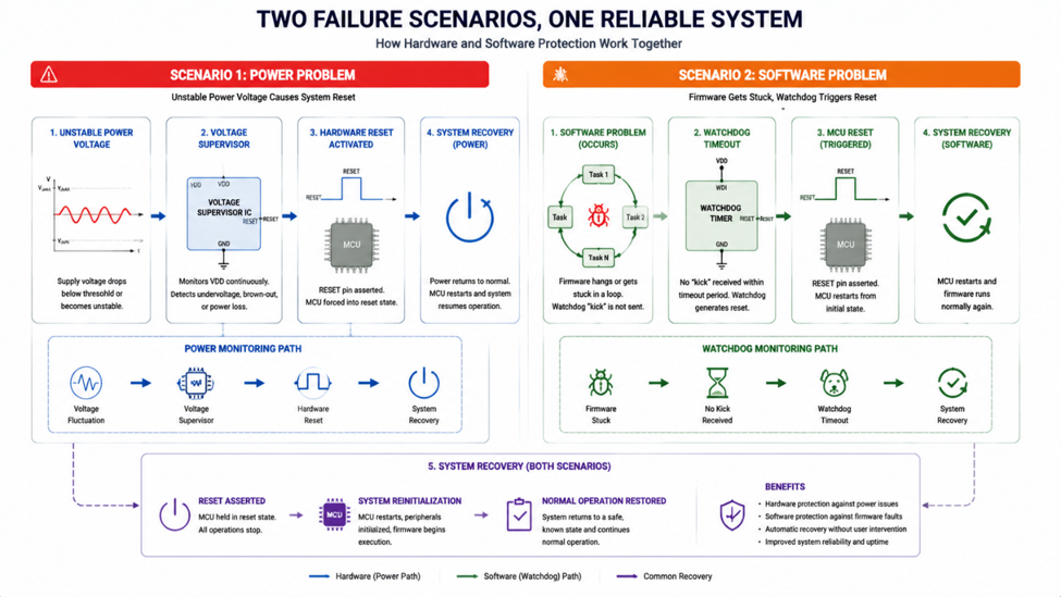
One of the most confusing problems with embedded systems is a device that randomly restarts without any obvious software error. The firmware appears stable, the code works correctly, and the circuit functions normally most of the time. However, the microcontroller suddenly resets during motor startup, wireless transmission, or when another load is activated.

In many cases, the problem is not the firmware it is the power supply stability.

A short voltage drop, known as a brownout, can force a microcontroller to restart automatically. Although the voltage dip may only last a few milliseconds, it can interrupt normal operation and create difficult-to-debug failures.

Understanding why brownouts happen and how to prevent them is an important part of reliable embedded system design.

image.png

Why Brownouts Happen

Microcontrollers can experience brownouts when the supply voltage temporarily drops below the minimum operating voltage.

Several situations can cause this:

  • Motors or relays are drawing a sudden current surge.
  • Wireless modules are transmitted at high power.
  • Weak power regulators.
  • Long power cables causing voltage drop.
  • Insufficient decoupling capacitors.

For example, an ESP32 may operate normally during idle mode but reset when Wi-Fi transmission begins because the current demand suddenly increases.

image.png

How to Prevent Brownout Resets

Preventing brownouts usually requires improving the power system rather than changing the firmware.

Common solutions include:

1. Improve Power Supply Capacity

The regulator should provide enough current with sufficient voltage margin. Choosing a regulator based on average current may cause problems during peak loads.

2. Add Proper Decoupling

Small ceramic capacitors near the MCU power pins help handle fast transient current changes, while larger capacitors provide additional energy storage.

3. Separate Noisy Loads

Motors, relays, and switching circuits should avoid sharing sensitive MCU power paths whenever possible.

4. Monitor Supply Voltage

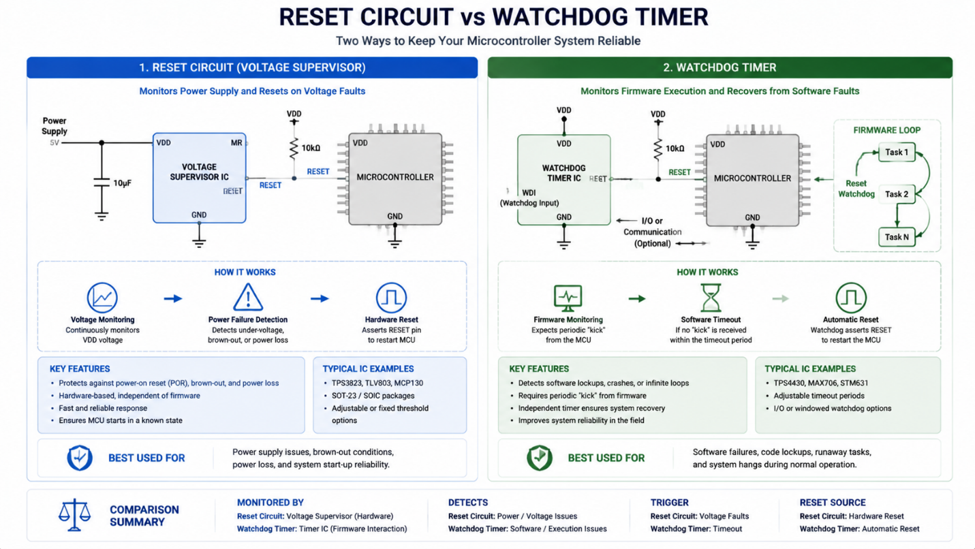
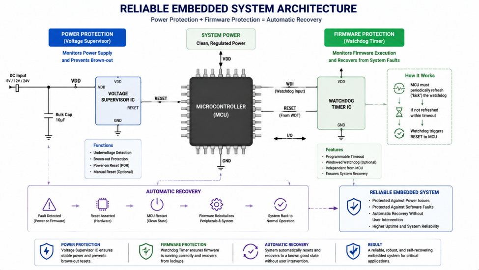
Some systems use voltage monitoring ICs or internal brownout detection features to ensure controlled recovery.

image.png

Recommended Devices

Device Type Typical Application
TPS62160 Buck Converter Compact MCU power supply
MCP1700 LDO Regulator Low-current embedded systems
TPS3839 Voltage Supervisor Reset monitoring
MAX809 Reset IC Microcontroller reset control

Engineering Tip

A reset problem that appears randomly is often a power problem in disguise. Before debugging firmware, check the supply voltage during the exact moment the failure occurs.

Brownout resets are one of the most common reliability issues in embedded systems. They are often caused by short voltage disturbances that are invisible when measuring only the average supply voltage.

By designing a stable power system, placing capacitors correctly, and understanding load behavior, engineers can prevent unexpected resets and build embedded devices that operate reliably in real-world conditions.

#EmbeddedSystems# #Microcontroller# #Brownout# #PowerIntegrity# #ESP32# #STM32# #Electronics#

Embedded Systems2
Why Your Power Supply Shuts Down When You Turn on a Device

A common situation in electronic systems is a device that works perfectly after startup but fails the moment power is applied. The power supply may shut down, the microcontroller may restart repeatedly, or the voltage may suddenly drop before returning to normal.

Many engineers initially suspect a faulty circuit or insufficient power supply capacity. However, the actual cause is often inrush current.

Inrush current is the temporary surge of current drawn by an electronic system immediately after power is connected. This short-duration event can be several times higher than the normal operating current and can stress power supplies, connectors, switches, and protection circuits.

Understanding inrush current is especially important in systems with large capacitors, motors, switching regulators, and battery-powered devices.

image.png


Why Inrush Current Happens

One of the most common causes of inrush current is charging large capacitors at the input of a circuit.

When power is first applied, an empty capacitor behaves almost like a short circuit for a moment. The power supply attempts to charge the capacitor as quickly as possible, causing a sudden current surge.

Other sources of inrush current include transformers, motors, LED drivers, and switching power converters with large input capacitance.

Although the event may only last milliseconds, it can trigger over-current protection or cause voltage instability in the entire system.

image.png

Common Protection Methods

Several techniques can reduce the impact of inrush current.

A simple method is adding an NTC thermistor, which has higher resistance when cold and lower resistance after heating. This limits the initial current surge while allowing normal operation afterward.

More advanced systems use soft-start circuits, load switches, or hot-swap controllers that gradually increase the applied voltage and control the startup sequence.

The correct solution depends on the application, required startup speed, current level, and reliability requirements.

image.png

Recommended Devices

Device Type Typical Application
MF72 Series NTC Inrush Limiter Power supply input protection
TPS22919 Load Switch Controlled power startup
TPS25947 Hot-Swap Controller Industrial power systems
LTC7000 Series Power Control IC High-current applications

Engineering Note

A power supply rated for the average operating current may still fail during startup if it cannot handle the temporary inrush current. Always check both steady-state and peak current requirements.

Inrush current is a temporary event, but its impact on system reliability can be significant. Understanding where startup current spikes come from and choosing the appropriate protection method can prevent unexpected resets, power supply failures, and damaged components.

Good power design is not only about supplying enough current during operation it is also about managing what happens the moment the system turns on.

#PowerAndEnergy# #InrushCurrent# #PowerSupply# #CircuitProtection# #PowerElectronics# #Electronics#

Power & Engery
Incremental vs Absolute Encoder: Choosing the Right Position Sensor

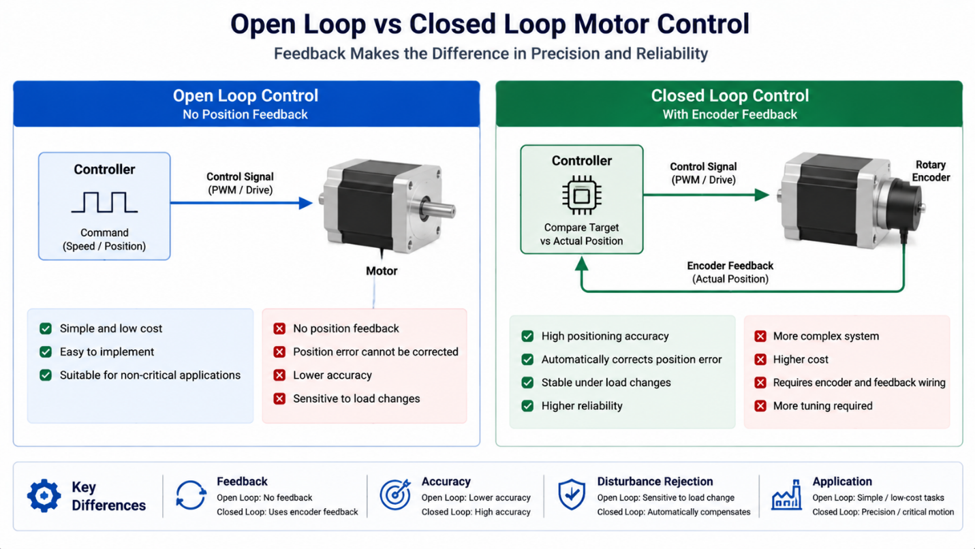
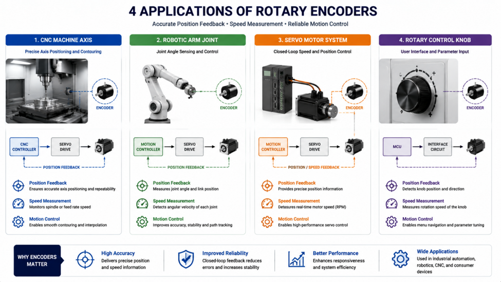
When a system needs to know the position or movement of a motor, simply detecting rotation is often not enough. Industrial machines, robotics, CNC systems, and automation equipment require accurate position feedback to control speed, direction, and movement.

Two common solutions are incremental encoders and absolute encoders. Although both measure rotation, they provide information in very different ways.

Choosing between them depends on whether the system only needs relative movement information or requires the exact position immediately after startup.

image.png

How Incremental Encoders Work

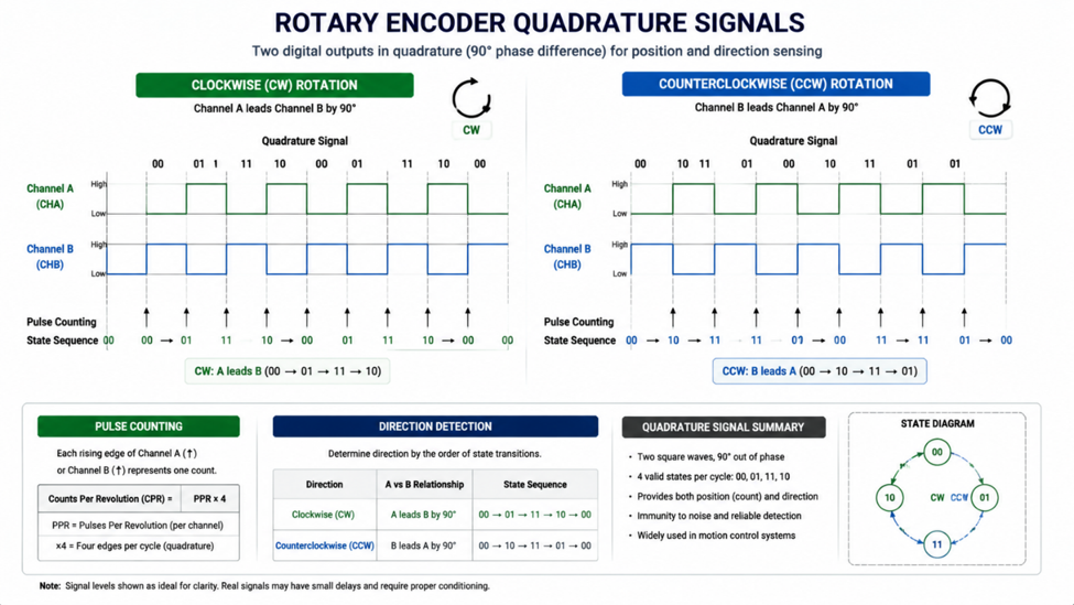
An incremental encoder generates pulses as the shaft rotates. The controller counts these pulses to determine movement distance and uses the phase difference between two channels (A and B) to determine rotation direction.

The main advantage is simplicity and cost. Because the output only represents changes in position, incremental encoders are widely used in motor speed control, conveyor systems, and motion applications where the reference position can be established during startup.

However, if power is removed, the controller loses the stored position unless the system performs a homing procedure.

How Absolute Encoders Work

An absolute encoder provides a unique digital value for each shaft position. Even after power loss, the system can immediately know the current position without needing to move back to a reference point.

This makes absolute encoders valuable in applications where position accuracy and startup reliability are critical, such as robotic arms, servo systems, and precision machinery.

The trade-off is increased cost and more complex communication requirements.

image.png

Quick Comparison

Feature Incremental Encoder Absolute Encoder
Output Pulse Signal Position Code
Startup Position Requires Reference Available Immediately
Cost Lower Higher
Complexity Simple More Advanced
Common Use Speed & Motion Control Precision Positioning

Recommended Devices

Device Type Typical Application
Omron E6B2-CWZ6C Incremental Encoder Motor speed and position
Autonics E40S Series Incremental Encoder Industrial automation
AS5048A Absolute Magnetic Encoder Precision rotary position
AMS AS5600 Absolute Magnetic Encoder Embedded position sensing

Engineering Tip

If your system can safely perform home after startup, an incremental encoder is often the more economical choice. If losing position after power failure is unacceptable, an absolute encoder is usually worth the additional cost.

Incremental and absolute encoders are not competitors; they solve different engineering problems. Incremental encoders provide a simple and cost-effective way to measure movement, while absolute encoders provide immediate position awareness and higher reliability. Selecting the correct type depends on the application's accuracy requirements, startup behavior, and system complexity.

#SensorsAndActuators# #Encoder# #MotionControl# #Automation# #EmbeddedSystems# #Electronics#

Sensors & Actuators
Design Maintenance Access into Your Hobby Machine

When building a hobby project like a CNC router or 3D printer, it's easy to focus on function and forget about future repairs. A few simple design choices now can save hours of frustration later. Start by avoiding permanent fasteners or adhesives on components that may need replacement, such as belts, bearings, or electronics. Use threaded inserts and machine screws instead of wood screws or glue for critical parts.

Think about access routes for tools. Leave enough space around fasteners to fit a wrench or Allen key. If a part is deep inside the frame, consider adding removable panels or hatches. For example, a small door on the side of a enclosure for the controller board allows you to swap it without disassembling the whole machine. Label wires and connectors clearly during assembly; this pays off when troubleshooting.

Another tip is to design for modularity. Mount subassemblies like the spindle or motor on separate plates that can be unbolted as a unit. This way you can remove the entire drive system without disturbing alignment. Also, plan for lubrication points. Add small access holes or zerk fittings for bearings that will need periodic greasing.

Finally, document your design with a simple sketch or photo. Note which fasteners need to be removed for each major component. This is especially helpful if you step away from the project for a while. With these habits, your hobby machine will remain easy to maintain and upgrade for years.

#DIYProjects# #Lubrication# #FinishingTechniques#

Mechanical Tips & Projects
PT2314 WiFi Audio Processor with ESP8266 Web Interface--from jlc--

Original article: PT2314 WiFi Audio Processor with ESP8266 Web Interface

8767908023660486656

PT2314 + ESP8266 audio processor board

I have been covering the PT series of audio DSP ICs PT2258, PT2315, and now PT2314. This one has 4 stereo input channels and a full tone control suite over I2C. Instead of front-panel knobs, I moved all controls to a web interface running on an onboard ESP8266. Volume, bass, treble, input selection, and gain are all adjustable from a phone browser. Settings are saved in EEPROM and survive power cycles.

PT2314 Overview

The PT2314 is a 4-channel audio processor from Princeton Technology (pin-compatible with TDA7314), controlled via I2C at address 0x44, supply 7.5–9V.

Key specs:

• 4 stereo input channels

• Input gain: 0 / +3.75 / +7.5 / +11.25 dB

• Volume: 0 to -78.75 dB (1.25 dB fine + 10 dB coarse steps)

• Bass / Treble: ±14 dB in 2 dB steps

• Speaker attenuation: 0 to -38.75 dB per channel

External components set the tone frequencies: 2.2nF ceramics for the treble shelving network and 5.6kΩ / 100nF pairs for the bass feedback loop.

Circuit and PCB

The board runs on 9V DC; an AMS1117-3.3 LDO steps it down to 3.3V for the ESP8266. AGND (pin 2) and DGND (pin 25) of the PT2314 share a single connection point and are separated in layout to prevent digital switching noise from coupling into the audio path. Ground fills on both layers, stitched with vias, reinforce this. I2C lines (SCL/SDA) are routed well away from all audio signals. PCB fabricated from JLCPCB.

8767907701680545792

Schematic — PT2314, ESP8266, LDO, and tone filter network

8767907742328086528

Two-layer PCB with ground fills on both sides

Firmware and Web UI

Firmware uses four libraries: Wire, EEPROM, ESP8266WebServer, and WiFiManager. On first boot the ESP creates a hotspot (PT2314_AudioAP / 12345678). Connect to it from your phone, pick your home WiFi in the captive portal, and from then on any browser on the network opens the control page.

The dark-theme UI has sliders for volume, bass, and treble plus input and gain selectors. Five built-in presets:

• Vocal: Bass 0, Treble +3

• Bass Boost: Bass +5, Treble -1

• Pop: Bass +1, Treble +2

• Rock: Bass +3, Treble +3

Slider moves hit the PT2314 over I2C in real time, so no page reload needed.

8767907814607986688

Dark-theme web UI on mobile browser

Testing

I tested with a Class-D amp and a Bluetooth module on Stereo Input 1. The Bluetooth output needed +7.5 dB input gain to level-match a direct AUX source. Audio was clean with no audible noise floor at normal listening levels. At high volume with bass boost maxed, the amp handled it without clipping.

Pop noise note: switching inputs or powering up produces a click. Make sure the downstream amp has a mute-on-startup feature, or add a relay delay on the speaker outputs. Battery supply gives the cleanest results; if using SMPS, add extra filtering on the 9V rail.

Electronic Tips & Projects