Designing a 3-Phase AC Current Data Logger for Industrial Load Monitoring

Three-phase electrical systems are widely used in industrial environments to power heavy loads such as motors, compressors, and production machinery. Monitoring current in each phase is essential to detect imbalance, overload conditions, and potential equipment failure.

In this project, a 3-phase AC current data logger was developed to measure, record, and analyze current consumption in real time using current transformers (CT sensors) and a microcontroller-based data acquisition system.

image.png

System Objective

The primary goals of the system are:

  • Measure RMS current for Phase R, S, and T
  • Detect phase imbalance
  • Log current data for analysis
  • Provide serial or IoT-based monitoring
  • Improve preventive maintenance capability

Hardware Architecture

Main components:

  • 3× Current Transformer (CT) sensors
  • Signal conditioning circuit (burden resistor + filter)
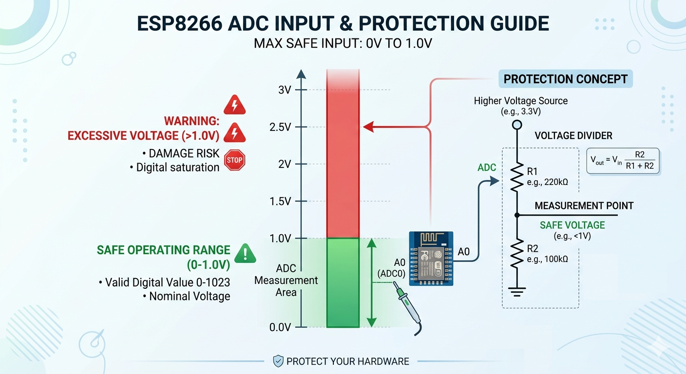
  • Microcontroller (ESP32 / Arduino)
  • LCD / OLED display (optional)
  • Data logging interface (SD card / Serial / IoT)
  • Isolated power supply

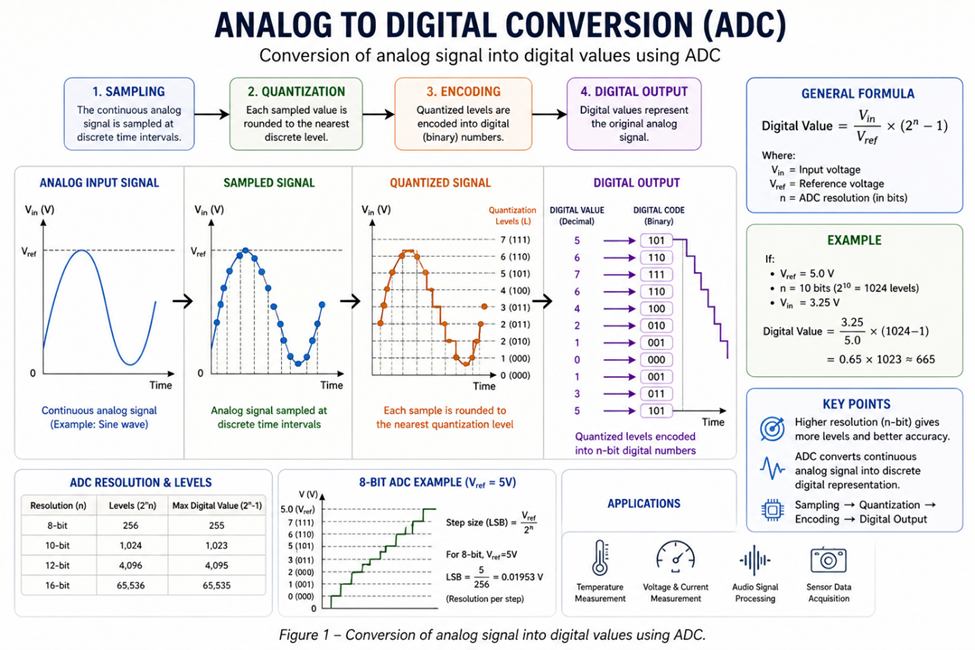
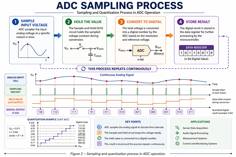
Each CT sensor converts AC current into proportional low-voltage AC signal. The signal is then conditioned and read by the microcontroller ADC.

image.png

CT Sensor (R,S,T) → Signal Conditioning → Microcontroller → Display / Logger

RMS Current Calculation

Because AC current is sinusoidal, RMS calculation is required.

Steps:

  1. Sample waveform at high frequency
  2. Square each sample
  3. Compute mean value
  4. Apply square root

Formula:

I_rms = √( (1/N) Σ i² )

image.png

This ensures accurate representation of effective current.

To improve stability:

  • Moving average filter applied
  • Zero-cross detection used (optional)
  • Noise reduction capacitor implemented

Phase Imbalance Detection

Phase imbalance occurs when one phase carries significantly different current from the others.

Imbalance percentage is calculated as:

Imbalance % = (Max Deviation / Average Current) × 100%

If imbalance exceeds threshold (e.g., 10%), warning flag is triggered.

This prevents:

  • Motor overheating
  • Reduced efficiency
  • Premature equipment failure

Data Logging Strategy

Several logging options can be implemented:

  • SD Card data storage
  • Serial monitoring via USB
  • CSV export for Excel analysis

image.png

Sampling interval is configurable (1–10 seconds depending on application).

Industrial Engineering Insight

Unlike simple ammeters, this system provides:

  • Continuous logging
  • Imbalance detection
  • Expandability to power calculation
  • Remote monitoring capability

It can be upgraded to:

  • Power factor monitoring
  • kWh energy calculation
  • Web-based dashboard
  • Alarm system

Conclusion

The 3-Phase AC Current Data Logger demonstrates a practical solution for industrial electrical monitoring. By combining accurate RMS computation, phase imbalance detection, and structured data logging, the system improves reliability and predictive maintenance capability.

Test & Measurement
Avoid PCB Layout Bottlenecks During Peak Projects

8737662723925065728

Project peak season hits, PCB layout suddenly becomes the biggest bottleneck?

❌PCB layout is usually the first thing to slow everything down—tight routing, hidden errors, and endless rework.

✅That’s where JLCPCB PCB Layout Services helps you get back on track.

#pcblayout# #pcbdesign# #hardwaredesign# #signalintegrity# #dfm#

Layout
Stuck on PCB Layout? Let JLCPCB Handle the Time-Consuming Step

8737654968971812864

Already have your schematic, but stuck on PCB layout—the step that looks simple but is actually the most time-consuming?

JLCPCB’s PCB layout service is here to solve that problem for you!

#JLCPCB# #PCB# #pcb layout# #pcb design#

Layout
Voltage converter 12V Into Dual-Rail 24V

I do love making circuits that can power my car amplifier from my car battery. Not just because it is 12V but my amplifier system needs a dual rail power. This is the major problem in transistor based amplifiers because they need a higher voltage with a stable ground reference thus a dual rail power supply concept comes and it hurts me more when I just have a simple 12V battery. Something like +24V and -24V. You need a way to step that up and split it into two symmetric rails. The obvious thing that came to mind is using a transformer that can do it.

8736836901635219456

That's exactly what this module does. It's a pre-built push-pull DC-DC converter board that takes 12V DC in and outputs 24-0-24V (that's +24V and -24V with a centre-tap ground) at over 5A. I picked one up for an amplifier project, and I thought it was worth breaking down how it actually works. The controller IC running the show is the KA3525A, a classic SMPS controller that has been around for decades. I will show here how the push-pull topology works, and how to wire it up safely. For real-world power-on and load testing.

How to Use It:

Connect your 12V DC source to the input terminals. This module does not have a reverse voltage protection feature. Use a source capable of supplying enough current. At 5A output on the 24V rails, the input side draws significantly more 10-12A from the 12V supply due to the step-up ratio plus conversion losses. Use thick wires (at least 14-16 AWG) and a source rated accordingly. A 12V lead battery or a beefy 12V switching adapter works well. Avoid unregulated wall warts.

8736836852062605312

Connect +24V and -24V to your amplifier's V+ and V- supply pins. The 0V centre-tap connects to your amplifier's ground. Some push-pull converters can develop voltage at no-load because the feedback loop. Start with a light load and verify the output voltages with a multimeter before connecting your amplifier.

My Experience:

I got this module to pair with an audio amplifier that needed dual +/-24V rails but I only had a 12V bench supply handy. It delivered on its core promise stable +/-24V rails from 12V input, powering the amplifier, I have checked it using a multimeter. As the output capacitor charges it shows a significantly higher around 25V. But I have also tested it under some load for which the results are given here.

8736836746655686656

Build quality is what you'd expect from a generic module. The PCB is decent, solder joints are acceptable, and the IRFZ44N MOSFETs are genuine. The transformer is the biggest component on the board and it's wired reasonably well. What you need to find is just a good component vendor in case you are building something like this on your own.

8736836804772102144

#power convertor# #voltageConvertor# #PCB#

Power & Engery
I Built a 100W Stereo Class-D Amplifier Using TPA3221

I am a fan of audio technology as it is cleared from most of my articles. I always try some new ICs or audio related things here. And today is the time for class D amplifiers. I made a subwoofer speaker that can handle upto 200W in stereo but I don’t have any good amplifier system that I can directly fit into my car. And that thing brings me towards TPA3221 IC. For the same price, anyone can get cheap Bluetooth speakers. But they distort at half volume, the bass rolls off a cliff. I want to drive my TP3221 amplifier directly from the car battery in this case.

8736804848261009408

So that it can actually push real power into real speakers, with clean audio and proper engineering behind it. The goal was simple: a compact, high-efficiency stereo amplifier that can deliver 100W per channel into 4-ohm speakers. Just a clean analog-in, speaker-out power amplifier that I could pair with any source. In this article, I will walk you through the full design. Schematic and PCB layout with a real-world audio test and listening demo, check out the YouTube video linked with this project.

Testing and Results

For the full audio test you can refer to the video attached here. I have tried music playback, frequency sweep, bass response, and real listening impressions with actual speakers. Audio quality is one of those things that does not translate well to text. You need to hear it. What I can say here at moderate listening levels, the amplifier is dead silent. No hiss, no hum, no audible switching noise. The closed-loop feedback does its job and the sound is noticeably cleaner than open-loop Class-D designs I have tried before.

#audio# #amplifier# pc #pcbdesign#

Design & Manufacturing
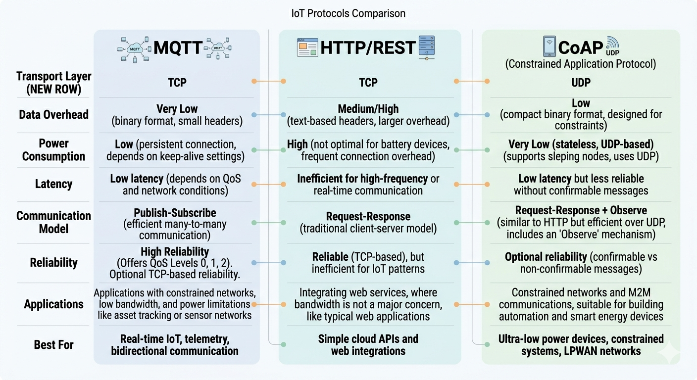
Start Your IoT Journey with ESP32 - Choosing the Right Communication Protocol

8736606615786098688

Most beginners focus on hardware first.

But in IoT, your protocol choice defines your entire system behavior.

Using a board like ESP32, you have multiple communication options—but they are not interchangeable.

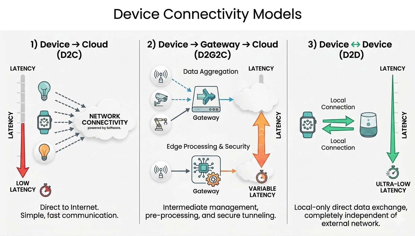
The Real Question

Not “How do I send data?”

But “What kind of communication does my system need?”

When to Use What

🌍 HTTP / HTTPS → Request–Response Systems

Use when:

  • You send data occasionally
  • You interact with REST APIs
  • You need compatibility with web services

Characteristics:

  • Simple
  • Reliable
  • Higher overhead

👉 Best for:

  • Data logging
  • Trigger-based communication

🔄 WebSocket → Real-Time Two-Way Communication

Use when:

  • You need continuous connection
  • Real-time updates matter
  • Low latency interaction

Characteristics:

  • Persistent connection
  • Full duplex (send + receive anytime)

👉 Best for:

  • Live dashboards
  • Remote control systems

📡 MQTT → Scalable IoT Communication

Use when:

  • Multiple devices communicate
  • You need low bandwidth usage
  • System must scale

Characteristics:

  • Publish/Subscribe model
  • Broker-based
  • Very lightweight

👉 Best for:

  • Sensor networks
  • Cloud-connected IoT systems

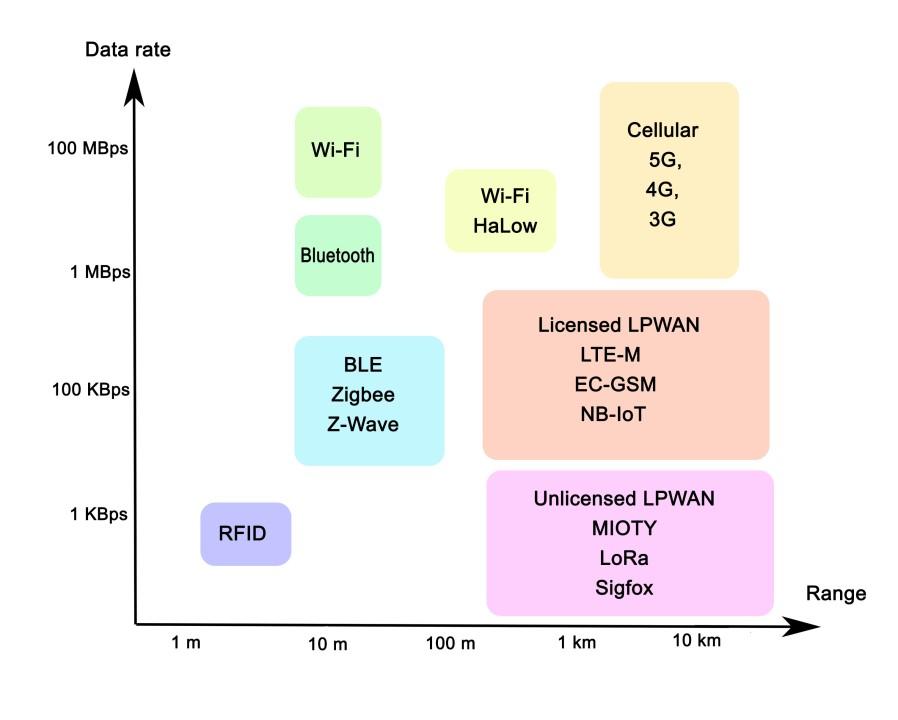
📶 BLE (Bluetooth Low Energy) → Short Range, Low Power

Use when:

  • Power consumption is critical
  • Communication is local
  • Mobile app interaction

Characteristics:

  • Low energy usage
  • Limited data rate
  • Short range

👉 Best for:

  • Wearables
  • Smart sensors

📲 Classic Bluetooth → Continuous Data Streaming

Use when:

  • You need stable, continuous data transfer
  • Power is less critical

Characteristics:

  • Higher throughput than BLE
  • More power consumption

👉 Best for:

  • Audio streaming
  • Serial communication replacement

📡 LoRa → Long Range, Low Data

Use when:

  • Devices are far apart
  • Infrastructure is limited
  • Data size is small

Characteristics:

  • Very long range (km-level)
  • Extremely low data rate

👉 Best for:

  • Agriculture monitoring
  • Remote sensing

🧠 The Core Insight

Protocol choice is a tradeoff between:

  • Range
  • Power
  • Latency
  • Data rate

You can’t optimize all four.

⚠️ Beginner Mistake

Trying to use one protocol for everything.

👉 Example:

  • Using HTTP for real-time control
  • Using BLE for long-range communication

This leads to unstable systems.


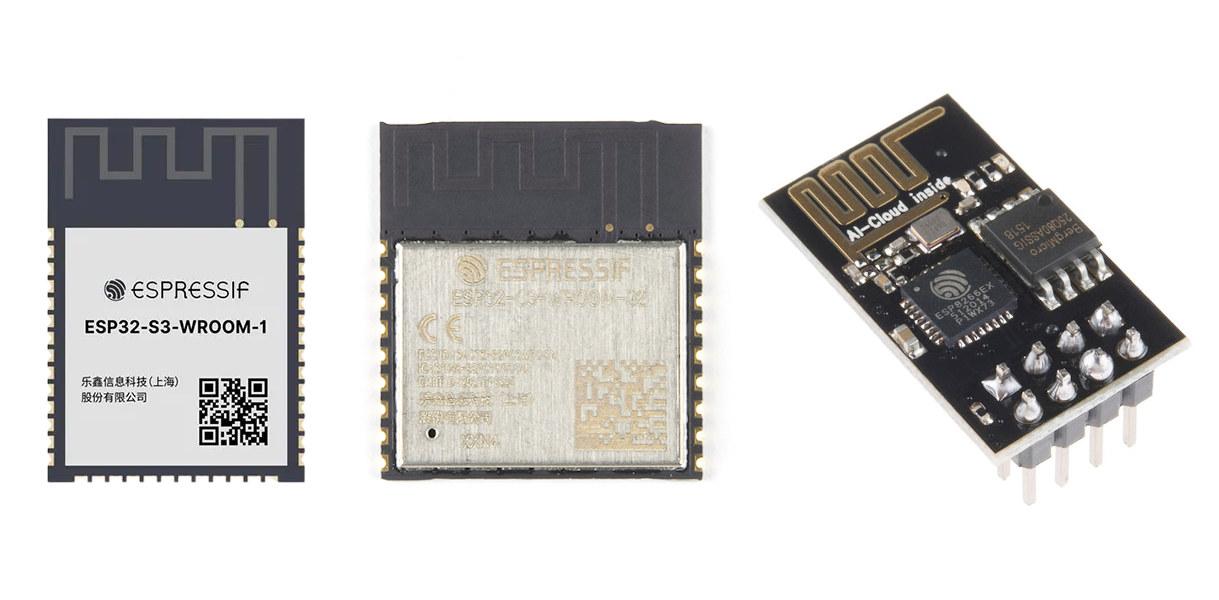
For more context about ESP32:

https://jlcpcb.com/blog/how-to-choose-an-esp32-development-board-beginner-friendly-guide
https://jlcpcb.com/blog/esp32-vs-arduino

Microcontrollers
Start Your Embedded Systems Journey - ESP32 or Arduino?

If you're starting embedded systems, the first confusion is:

👉 “Should I begin with Arduino or ESP32?”

Here's the simplest way to decide without getting overwhelmed.

Step 1: Learn How Hardware Works

Start with → Arduino Uno

Why this is the best starting point:

  • No WiFi, no background complexity
  • Code runs step-by-step (easy to debug)
  • Helps you understand:
    • GPIO (input/output)
    • sensors
    • actuators (LEDs, motors)

Programming Language (Arduino)

  • Uses C/C++ (Arduino-style)
  • Simplified functions:
    • setup()
    • loop()

👉 Very beginner-friendly—no need to manage OS or multitasking


Step 2: Build Real Connected Systems

Move to → ESP32

Why upgrade to ESP32:

  • Built-in WiFi + Bluetooth
  • Supports multitasking (FreeRTOS)
  • Suitable for real applications:
    • IoT
    • remote control
    • cloud integration

Programming Language (ESP32)

  • Also uses C/C++ (Arduino IDE or ESP-IDF)
  • Advanced features:
    • multitasking (FreeRTOS)
    • networking stacks

👉 Slightly more complex, but much more powerful

Beginner Project Roadmap

Level 1 (Arduino)

  • Blink LED
  • Button input
  • Temperature sensor
  • Motor control

👉 Goal: Learn hardware + basic C/C++ logic

Level 2 (ESP32)

  • Web server (control LED from browser)
  • WiFi sensor dashboard
  • Bluetooth control

👉 Goal: Learn networking + system design

Common Beginner Mistake

Starting directly with ESP32:

  • More complex debugging
  • Background tasks (harder to understand)
  • Requires better coding understanding

👉 Result: confusion instead of learning


The Smart Learning Path

Arduino → Learn C/C++ basics + hardware
ESP32 → Apply it to real connected systems

For a deeper comparison:
https://jlcpcb.com/blog/esp32-vs-arduino

8736603601482555392

Microcontrollers
Microcontroller vs Microprocessor - Project-Based Selection Guide

8736599939083001856

Instead of theory, here's how to choose based on real project scenarios:


🔋 Project 1: Battery-Powered IoT Sensor Node

(e.g., temperature + humidity + LoRa/WiFi)

Choose → Microcontroller (MCU)

Why:

  • Ultra-low power (µA sleep modes)
  • Built-in ADC, GPIO, communication interfaces
  • Instant wake-up (no OS overhead)

📌 Examples:

  • ESP32
  • STM32L4

🤖 Project 2: Motor Control System

(e.g., BLDC motor, robotics, inverter)

Choose → Microcontroller (MCU)

Why:

  • Deterministic real-time control
  • Precise PWM + timers
  • Low latency interrupt handling

📺 Project 3: Smart Display / HMI System

(e.g., touchscreen UI, dashboards)

Choose → Microprocessor (MPU)

Why:

  • Requires OS (Linux/Android)
  • Handles graphics + touch + networking
  • Needs external RAM

📌 Example:

  • Raspberry Pi 4

📷 Project 4: Camera / Vision System

(e.g., face detection, surveillance)

Choose → Microprocessor (MPU)

Why:

  • High data throughput
  • Image/AI processing
  • Large memory + OS support

🔌 Project 5: Power / Energy System

(e.g., solar controller, UPS, BMS)

Choose → Microcontroller (MCU)

Why:

  • Analog sensing (voltage/current)
  • Real-time control loops
  • High reliability

🌐 Project 6: IoT Gateway / Edge Device

Choose → Microprocessor (MPU)

Why:

  • Runs Linux + networking stack
  • Handles multiple devices + protocols
  • Cloud connectivity + local processing

🔄 Project 7: Smart Industrial System (MCU + MPU Together)

(e.g., industrial automation panel, smart EV charger, advanced robot)

Choose → Hybrid (MCU + MPU)

Architecture:

  • MCU → Real-time control layer

    • Sensors, actuators, safety loops
  • MPU → Application layer

    • UI, cloud, analytics, networking

Why this split works:

  • MCU guarantees deterministic timing
  • MPU handles complex processing + OS tasks
  • Improves system reliability and scalability

📌 Example combination:

  • MCU: STM32F4
  • MPU: Raspberry Pi 4

📌 Communication between them:

  • UART / SPI / CAN / Ethernet

🔥 Core Decision Rule

Control + Real-time → MCU
Processing + OS + UI → MPU
Both needed → Split architecture (MCU + MPU)


🚀 Final Takeaway

  • MCU = Efficiency, control, low power
  • MPU = Performance, flexibility, complex systems
  • MCU + MPU = Industrial-grade architecture

👉 Most advanced products today use a hybrid approach.


🔗 Reference

For a more detailed breakdown:
https://jlcpcb.com/blog/microcontroller-vs-microprocessor

Embedded Systems2
No welding needed - choose flexible and lightweight solutions!

Just bolts, nuts, and standard components to quickly assemble sturdy and flexible structures. https://jlcmc.com/campaign/aluminum-profile?from=snsprofile JLCMC modular aluminum systems, perfect for modular and lightweight designs that save cost and time!✨

💡 T-Slot Design: Connect, adjust, and expand your structures

🛠Angle Brackets: Secure 90° or custom angles easily.

⚙️Expand Functionality: Casters or leveling feet for mobility or stability

8735226864070352896

Mechatronic Components
Practical Guide: How to Select a Supercapacitor Bank with a 12V Battery System

In a real supercapacitor vs battery design, the goal is to choose a supercapacitor that can handle startup current spikes without causing voltage sag or stressing the battery. Selection is based on three parameters: voltage, capacitance, and ESR.

1. Voltage Rating (Series Cells)

Supercapacitors are rated ~2.5–2.7V per cell, so series connection is required.

  • 12V system peak ≈ 14.4V
  • Required cells: 14.42.7≈ 6

Design choice:

  • Use 6–8 cells in series (≈16V rated bank)
  • Include cell balancing (passive or active) to prevent overvoltage

2. Capacitance (Farad Selection)

Capacitance determines how effectively voltage sag is reduced during transients.

Note: Despite high capacitance (F), supercapacitors store less energy than batteries due to lower voltage.

Quick sizing guideline:

  • Small loads → 0.1–1 F
  • Medium loads → 1–10 F
  • High surge (motors, inverters) → 10–50 F+

Oversize by ~2× for stability and aging margin

3. ESR (Critical for High Current)

Voltage drop under load: V=I×ESR

Example: 20A × 0.1Ω = 2V drop (unacceptable for 12V rail)

Target ESR:

  • Moderate load → < 50 mΩ
  • High surge → < 10–20 mΩ

4. Choosing Supercapacitor Type

  • Cylindrical EDLC cells → best flexibility and performance
  • Pre-balanced modules → simpler integration for higher voltage systems

5. Pre-Charge the Supercapacitor Bank (Critical Step)

A discharged supercapacitor behaves like a near short circuit, causing dangerous inrush current if directly connected.

Procedure:

Step 1: Insert a pre-charge element

  • Power resistor (5–50Ω, high wattage) or NTC thermistor

Step 2: Estimate initial current: I_initial=V✖R

  • Example: 12V / 10Ω ≈ 1.2A (safe)

Step 3: Allow gradual charging:

  • Time constant: τ=R✖C

Step 4: Monitor voltage

  • Wait until: Supercapacitor voltage ≈ battery voltage (within ~0.1–0.2V)

6. Switch to Direct Parallel Connection

Once pre-charged:

  • Bypass the resistor using:

    • Relay / contactor (simple)
    • MOSFET switch (preferred for modern systems)

*******Connection sequence:

  1. Pre-charge through resistor
  2. Verify voltage match
  3. Close bypass switch

→ Supercapacitor now directly in parallel


8734577937826775040

Figure: Circuit schematic of a 12V wind turbine hybrid power system. It details a 12V battery connected in parallel with a 6-cell supercapacitor bank, featuring a current-limiting pre-charge resistor and a bypass switch to safely manage inrush current.

⚠️ Engineering Notes

  • Never connect a 0V supercapacitor directly to a battery

  • Use proper wire gauge (high current path)

  • Keep connections short (minimize inductance)

  • Add protection:

    • Fuse or current limiting if required

\

Result

  • Supercapacitor handles startup surge current

  • Battery provides continuous energy

  • System avoids:

    • voltage sag
    • battery stress
    • premature degradation

Key Takeaway: Always pre-charge a supercapacitor before connecting it in parallel with a battery - this prevents destructive inrush current and ensures stable hybrid operation.

Learn More: https://jlcpcb.com/blog/supercapacitor-vs-battery

**##supercapacitor# ##battery# ##supercapacitor_vs_battery#**

Power & Engery
Handheld accurate sound level dB meter

Because I am a sound lover, and in recent times I have done a lot of research on audio-related products. But I am always curious to measure the sound performance in terms of dB(A). In that way, when the amplifier is in steady state, I can measure the total output noise due to the surroundings. Because decibels are a logarithmic scale, it usually starts from a very light value, and it can also measure very high values. I have many options, as someone on the internet says, there are phone apps that claim to measure sound levels, but let's be honest, a phone microphone is designed for voice calls, not calibrated acoustic measurement.

So if you want to measure actual sound output, there are professional sound level meters, but they start at a couple of hundred dollars. But I wanted something in between a handheld dB meter that's actually accurate and battery-friendly. When I was searching the web, I came across the DFRobot Gravity Analog Sound Level Meter. This little board has a professional-grade MEMS microphone with proper signal conditioning. It has an A-weighting filter and a beautifully simple analog output. The voltage coming out is linearly proportional to decibels. So, no complex DSP, no FFT, just read an analog pin and multiply. I paired it with my own designed Arduino from JLCPCB and a 0.96" OLED display, and that’s how I got myself a proper handheld dB meter.

How the Code Works:

Because the sensitivity and conversions are based on ADC and they work on a reference. If that reference voltage is stable the readings are accurate. Arduino's 5V rail can vary from 4.6V to 5.2V depending on the host. And when running on battery, over the time as the battery discharges, there will be variations. To eliminate this issue, we used the `readVcc() function which takes the reference from the internal 1.1V bandgap of Arduino. This gives us the true supply voltage in millivolts, which we use in the dB calculation.

Raw sensor readings can be noisy. The code uses a circular buffer of 10 samples to compute a running average. This smooths out spikes while still responding quickly to changes (10 samples x 125ms = 1.25 seconds of averaging).

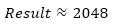
Here is how the ADC conversion is done:

A perfectly linear 0.6V-to-2.6V range mapping to 30-130 dBA. No lookup tables, no polynomial curve fitting, no complex calibration. Just multiply by 50. That's it. 0.6V = 30 dBA, 2.6V = 130 dBA.

dbValue = (analogRead(A0) / 1024.0) \* Vref \* 50.0;

Testing and Working:

I have tested the output in different scenarios, and it is working perfectly. Best to pair it directly with the Arduino with a soldering connection; a loose one may give you noise.

Testing with Songs:

8734494598990336000

Testing during conversation:

8734494663079571456

#PCB# #SOUND# #DB METER#

Analog & Signal