Electronic Community
-
Mechanical Community
-
JLCPCB
-
JLC3DP
-
JLCCNC
-
JLCMC
-
JLCONE
-
EasyEDA


Add 2 or 3 IMUs in Flight Controller
Have more than 1 IMU in Flight controller sound the best practical solution instead of using only 1 IMU because it can be increase their stabilization and accuracy right? Is it possible? The answer is YES. Since the IMU using a SPI communication, you can added more than 1 IMU into your Flight Controller. This is the example that if you use 2 IMUs configuration.
The question is, How this can be programmed into our Flight Controller?
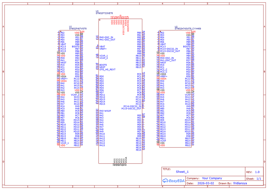
You can programmed based on C++ on STM32CubeIDE, but you should refering to Ardupilot and define into your firmware what the IMU Series that you used in your flight controller. But remember, don't you use the same series an IMU. I recomened you use different IMU and select it based on the best practical used from their manufacture and datasheet. for example IIM-42652 has industrial grade standrad for the main IMU, ICM-42688P is the accurate IMU sensor to compare the data. For the fusion both of two IMU, you should use the Kalman Filter. A Kalman filter enhances IMU data by optimally combining sensor measurements and system dynamics to reduce noise and improve estimates of orientation, velocity, and position. If you want to refer on Industrial Flight controller that used 2 or 3 IMUs, this is Cube Orange Plus for the example from Ardupilot website. The Cube Orange/+ With ADSB-In Overview — Copter documentation
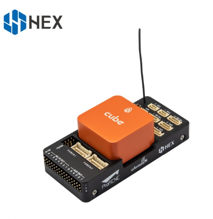
Cube Orange Plus use 2 IMU in their Board (Invensense ICM42688 IMU and ICM20948 IMU/MAG), looked into Specification on the website.
Choosing the Right IMU for Your Application
When selecting an IMU, consider the following factors:
- Degrees of Freedom (DoF) – Most IMUs come in 6-DoF (accelerometer + gyroscope) or 9-DoF (accelerometer + gyroscope + magnetometer) configurations.
- Accuracy & Sensitivity – Higher-end IMUs provide lower drift and better precision.
- Power Consumption – Critical for battery-powered applications like wearables and drones.
- Interface Compatibility – Ensure compatibility with microcontrollers, SoCs, or FPGA-based systems.
6 Axis vs 9 Axis IMU
The 9 Axis maybe sound better than 6 Axis for Flight Controller IMU right? But it doesnt necesarry at all, it depends on your necessity.
6 Axis: three-axis (XYZ) accelerometer + three-axis (XYZ) gyroscope (also called angular velocity sensor)
9 Axis IMU (AHRS) Combines Accelerometer, Gyroscope, and Magnetometer (3+3+3 axes) to provide total orientation (Roll, Pitch, Yaw). They used Algorithms (Kalman Filter, Madgwick) to fuse data: Accel gives gravity vector (Roll/Pitch), Mag gives North (Yaw), and Gyro provides fast updates and smoothing. For the example, the 9 Axis IMU is using for VR/AR tracking, sophisticated drone control, robot localization, etc.
So 6 Axis module can form VRU (Vertical Reference Unit) and IMU (Inertial Measurement Unit), 9-axis module can form AHRS (Attitude Reference System).
LSM9DS1 is the example for 9 Axis IMU, it combines 3D accelerometer, 3D gyroscope, 3D magnetometer into single chip.
The 9-axis IMU is a key component of advanced sensor fusion, forming the foundation for accurate insights across various applications. By integrating sensor fusion software and AI algorithms, industries can achieve higher standards of accuracy and efficiency.
Pro Tips
To make your guide even more valuable for beginners, consider adding these "Flight Controller" secrets:
- Power Integrity (The LDO Factor): Mention that IMUs are extremely sensitive to power noise. Beginners should use a dedicated Low-Dropout Regulator (LDO) with high PSRR (Power Supply Rejection Ratio) specifically for the IMU to prevent "gyro drift" caused by noisy power from the motors.
- Trace Routing: Advise them to keep the SPI traces as short as possible and to keep them away from high-current paths (like the battery leads or ESC signals) to avoid electromagnetic interference (EMI).
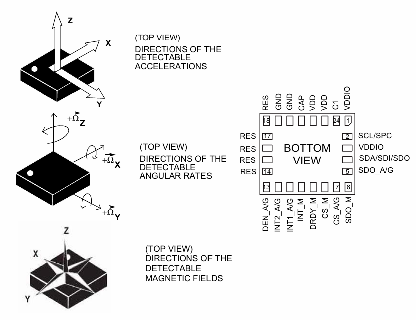
- Mechanical Orientation: Remind them to look for the small dot on the chip. In the drone world, the orientation of the IMU on the PCB must be known so that the firmware can be configured to know which way is "Forward" (X), "Left/Right" (Y), and "Up/Down" (Z).
- The "Ground" Warning: Regarding advice to ground the INT pin add a small disclaimer. Some IMUs might drive that pin HIGH by default; it is safer to suggest a 10k Ohm pull-down resistor rather than a direct short to ground to prevent accidental hardware damage during firmware boots.
What Is an Inertial Measurement Unit (IMU)?
An Inertial Measurement Unit (IMU) is an electronic device that measures and reports acceleration, angular velocity, and sometimes magnetic field data. It typically consists of:
- Accelerometers – Measure linear acceleration along the X, Y, and Z axes.
- Gyroscopes – Detect angular velocity to track orientation changes.
- Magnetometers (optional) – Provide heading data by measuring Earth’s magnetic field.
By combining these sensor readings, an IMU can determine an object’s movement and positioning, making it essential for applications requiring precise motion tracking.
Application in Flight Controller
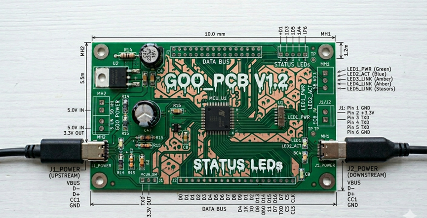
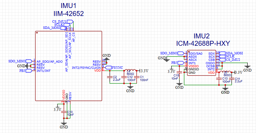
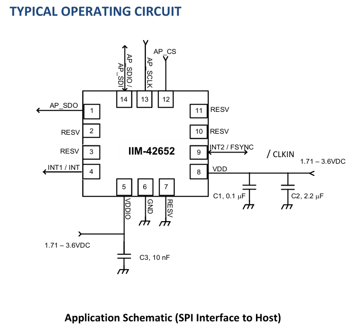
This is a typical implementation of an IMU within a Flight Controller using EasyEDA. For supporting circuits like decoupling capacitors, you should refer to the "Typical Application" section in the IMU datasheet. In this example, I am using the IIM-42652, an industrial-grade IMU designed for high-performance flight controllers. You can access the datasheet here:
IIM-42652 Datasheet(PDF) - TDK Electronics.
Most commonly, IMUs in this field use SPI communication instead of I2C due to its superior speed. While SPI requires more pins specifically CS (Chip Select), SDO/MISO, SDA/MOSI, and SCLK the performance trade-off is worth it.
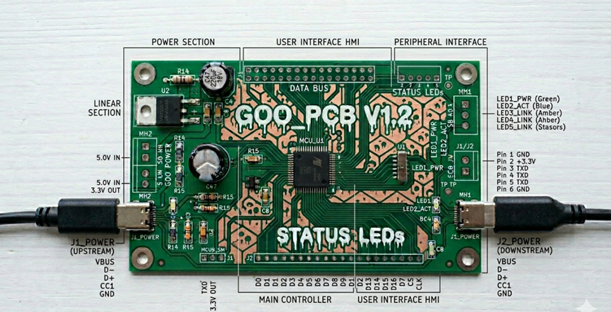
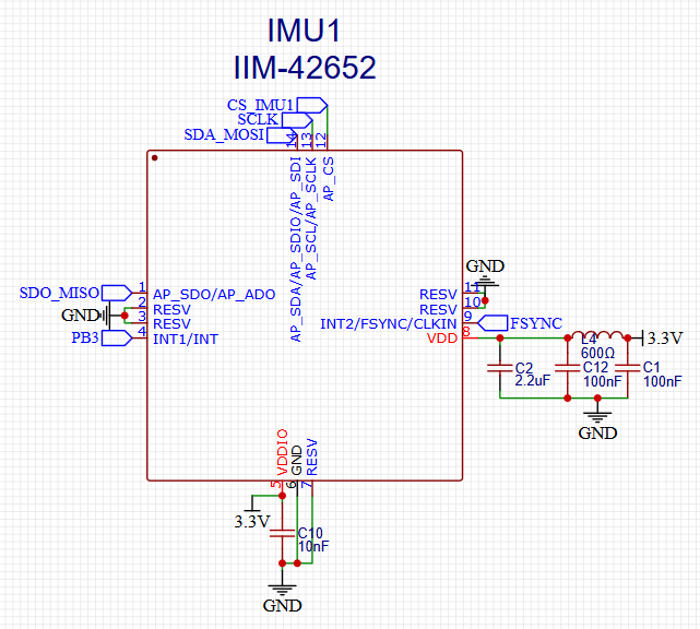
Most commmonly IMU are using SPI communication instead of I2C or others. this probably needs more Pins, such as CS, SDO/MISO, SDA/MOSI, SCLK. Maybe you asking for INT and FSYNC why they still connected into a netlabel (which is conneted into MCU). The reason is depend on the IMU that you using for. INT (interrupt) is a digital output pin from the IMU that signals the microcontroller when a specific event occurs, so the MCU doesn't have to constantly poll the IMU, saves CPU time and power by avoiding continuous polling, and the MCU can sleep until the IMU signals new data. You can use this pin when your MCU (especially STM32) still have pins that not used, but if not you can float this pin or connected this pin into the ground (check the datasheet for the best termination), but using it is highly recommended for efficiency.
FSYNC (Frame Synchronization) is a hardware pin and feature used to synchronize sensor data sampling with an external event or device. Basicly it Aligns IMU data samples with an external timing reference (e.g., a camera frame, GPS pulse, or another sensor). But you should be looked at Hwdef.dat to see is the IMU compatible with the Ardupilot environment or not.
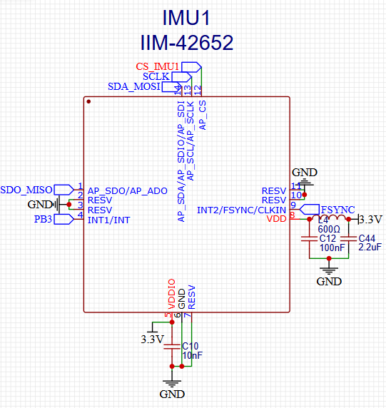
Maybe you asked for why I added Ferrite Bead 600 Ohm in Power Rail input for IMU, which is not enter in the datasheet (see the figure in bottom).
The reason is for filtering the circuit from noise suppression. A ferrite bead is not an ideal inductor, its main purpose is not to“reflect noise and block it.”So It works by dissipating high-frequency energy as loss (heat), that is why ringing is reduced and the waveform settles faster. But because of the oscillation, you should know which the frequency that you used in the circuit (is it High or Low Frequency) and find the Capacitor for the Pi-Filter. This is the Figure that shown Pi Filter used a ferrite bead and two 100nF Capacitor.
Maybe we can discuss how the Pi Filter work and how to choose the value, connected and layouting them. If youre interested you can watch this video from Robert Ferenac and explained by Eric Bogantin https://youtu.be/HaLMjVkKYMw?si=AxCk40LLvW4WpBE9. But the conclution is, the ferrite bead is important to block the noise thatr can be caused an error data IMU which is can be caused a weird moving into your UAV later.


In this article https://jlcmc.com/blog/m3-m6-screws-a-complete-guide-and-their-applications, we break down the differences and best use cases for M3 to M6 screws. Plus, you can grab a complete screw kit from JLCMC starting at just $6.7 per set.
🟢Size & Load: M3 for small & precise jobs; M4 & M5 for medium-duty; M6 for heavy-duty applications.
⚙️Thread Pitch: Finer threads for precision (M3), medium for versatility (M4–M5), coarse for high load (M6).
💪Strength: M3 for light indoor use, M4–M5 for moderate strength, M6 for high-stress projects like machinery or automotive.
From precision electronics to heavy-duty industrial equipment, the right screws play a critical role in keeping everything together. Selecting the correct size and material doesn't just ensure a secure fit—it boosts performance and makes your projects way more efficient!