Electronic Community JLCDMP Mechanical Community OSHWLab JLCPCB JLC3DP JLCCNC JLCMC JLCONE EasyEDA JLCCAN LCSC Cable LCSC Panel



In this article https://jlcmc.com/blog/m3-m6-screws-a-complete-guide-and-their-applications, we break down the differences and best use cases for M3 to M6 screws. Plus, you can grab a complete screw kit from JLCMC starting at just $6.7 per set.
🟢Size & Load: M3 for small & precise jobs; M4 & M5 for medium-duty; M6 for heavy-duty applications.
⚙️Thread Pitch: Finer threads for precision (M3), medium for versatility (M4–M5), coarse for high load (M6).
💪Strength: M3 for light indoor use, M4–M5 for moderate strength, M6 for high-stress projects like machinery or automotive.
From precision electronics to heavy-duty industrial equipment, the right screws play a critical role in keeping everything together. Selecting the correct size and material doesn't just ensure a secure fit—it boosts performance and makes your projects way more efficient!

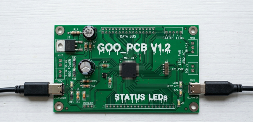
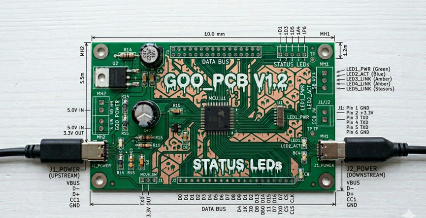
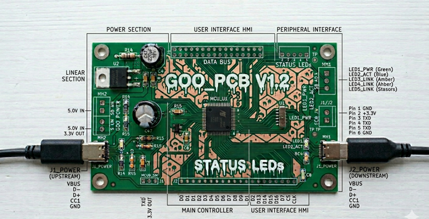

Another newbie to EasyEDA. I created a schematic for a board with 2 DPDT relays and a few other parts (snubber diode, LED/resistor, etc.) where the relay NO, Common and NC connections are intended to have pads for external wiring. They are intended to carry fairly heavy current so I set the Pads at 3mm and Holes at 1.789mm. I couldn't find anything for the schematic for a pad output, so I left them unattached. When I created the PCB, I added the Pads and Tracks. However the DRC check shows Errors, (Picture here) 31 of them for the pads and the traces that I added. I couldn't find out why!!!
So, I went back to the schematic and re-created the PCB and tried to add just one connection , and of course it shows a DRC Error:
gge3254-gge3248 (-3mm, need more than DRC (0.152mm)
A picture of the Error is here. (I couldn't get the forum to show the picture) This is the single error just to play with but I can't find a solution. I can't figure out what to do!
I have another VERY similar board that I created and it doesn't have any errors, shown here.
Mike
#PCB#