Electronic Community Mechanical Community OSHWLab JLCPCB JLC3DP JLCCNC JLCMC JLCONE EasyEDA JLCCAN LCSC Cable LCSC Panel

Original Instructables article: https://www.instructables.com/One-Button-Based-5-20V-USB-C-PD-Voltage-Selector/
I have worked with the CH224K USB PD sink controller before, a tiny IC that handles the entire PD negotiation for you. My previous build used fixed resistors to set the voltage. This time I wanted something more practical: a single-button selector that cycles through 5V, 9V, 12V, 15V, and 20V with LED indicators for each. The MCU I paired it with is the CH32V003F4P6 — a 32-bit RISC-V chip from WCH that costs about $0.10.
How It Works
The CH224K handles USB PD negotiation over the CC lines in the USB-C connector. Three configuration pins (CFG1, CFG2, CFG3) tell it which voltage to request from the charger. Drive these with a microcontroller and you can change voltage on the fly. The lookup table:
• 5V: CFG1=1, CFG2=X, CFG3=X
• 9V: CFG1=0, CFG2=0, CFG3=0
• 12V: CFG1=0, CFG2=0, CFG3=1
• 15V: CFG1=0, CFG2=1, CFG3=1
• 20V: CFG1=0, CFG2=1, CFG3=0
CH224K key features: supports PD 2.0 and 3.0, selectable 5–20V output, built-in CC pull-down resistors, Power Good (PG) output, SOP-10 package.
MCU — CH32V003F4P6
The CH32V003F4P6 is a QingKe 32-bit RISC-V MCU at ~$0.10, chosen deliberately so the controller does not cost more than the function it provides. It runs at 48MHz with 16KB flash, 2KB SRAM, and 18 GPIO pins. For this project I use 9 pins: 3 for the CH224K CFG lines, 5 for indicator LEDs, and 1 for the push button.
An LM317 linear regulator converts the variable PD rail (5–20V) to a stable 3.3V for the MCU supply. Critical note: set the LM317 potentiometer to 3.3V before soldering the MCU, powering it at an incorrect voltage will destroy the chip.
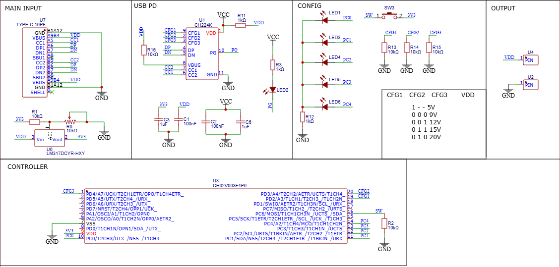
Schematic — CH224K CFG lines, LM317 supply, LEDs
Firmware
The firmware is minimal C written in WCH's MounRiver Studio. Three lookup arrays map mode index (0–4) to CFG pin states and the active LED pin. On each button press, the code reads the GPIO, applies a 20ms debounce delay, increments the mode index (wrapping at 4), then calls applyMode(). That function clears all LEDs, drives the three CFG pins from the lookup tables, and lights the correct LED. Boot defaults to 5V — the safest starting voltage since every PD charger supports it.
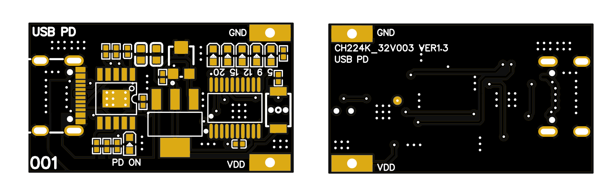
Compact 2-layer PCB from JLCPCB — USB-C left, LEDs and button right
Testing
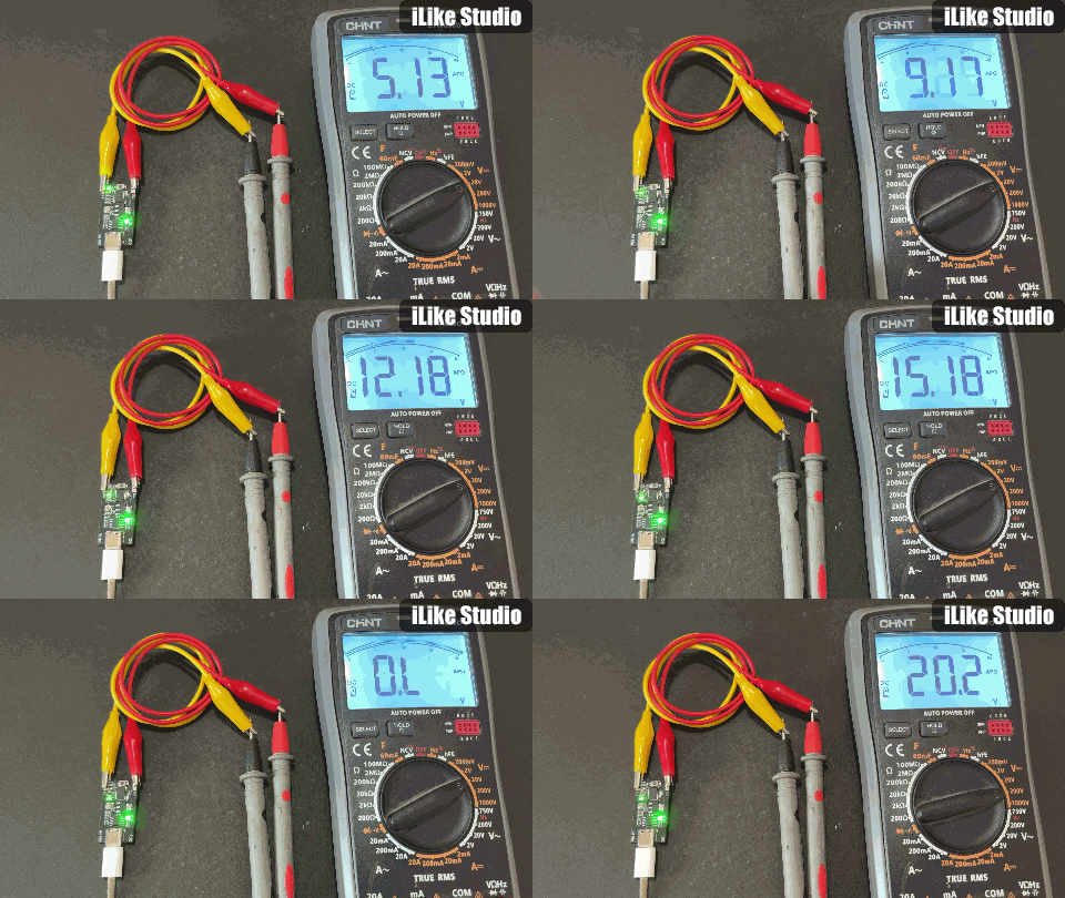
I brought up the board with a USB meter in series for overcurrent protection. It worked first try. After confirming idle current, I switched to the charger directly and measured all five voltages with a multimeter, each one correct on button press.
Original Hackster article: https://www.hackster.io/sainisagar7294/lm358-based-simple-waveform-generator-79af29
LM358 waveform generator — square and triangular outputs
I needed a quick bench tool to verify small circuits and ICs without spending $50+ on a function generator. So I built one from a single LM358 op-amp for square and triangular waves up to 5kHz, for under $2.
Circuit
The design uses a Schmitt trigger relaxation oscillator for the square wave. R1 controls the capacitor charge/discharge time and sets the base frequency range. R2 and R3 form a voltage divider that sets the waveform midpoint reference (the ground line). A 100kΩ potentiometer makes frequency variable within the range.
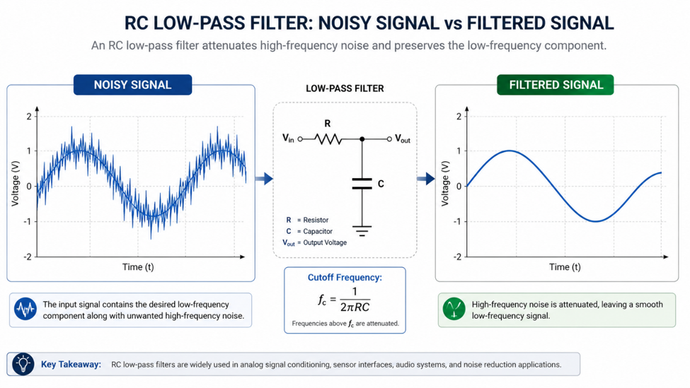
A series RC integrator (R4 + C2) converts the square output into a triangular wave. The RC time constant must be larger than the square wave period, otherwise the capacitor does not have enough time to form a clean ramp.
Amplitude vs. Frequency
The triangular wave amplitude is inversely related to frequency. At low frequencies, the capacitor charges more per half-cycle and gives a larger swing. At high frequencies, it barely charges before polarity flips and the output shrinks. This is inherent to RC integration. Adding a second integrator stage approximates a sine wave, but amplitude drops sharply above 1kHz. For stable sine output, a Wien bridge or Hartley oscillator is the better choice.
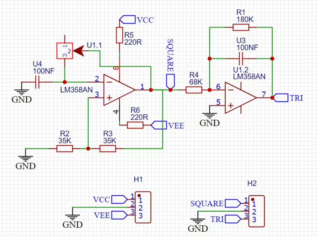
Schematic — square wave generator with RC integrator
Components and PCB
Components needed:
• LM358 op-amp
• Resistors: 180kΩ, 68kΩ, 39kΩ, 220Ω
• 100nF capacitor
• 100kΩ potentiometer
• Dual-rail power supply
PCB designed in EasyEDA. Square wave amplitude scales with supply voltage. For a fixed-amplitude triangular output, add a third op-amp gain stage on the output. Gerbers available in the original article, change R1/C1 values to shift the frequency range.
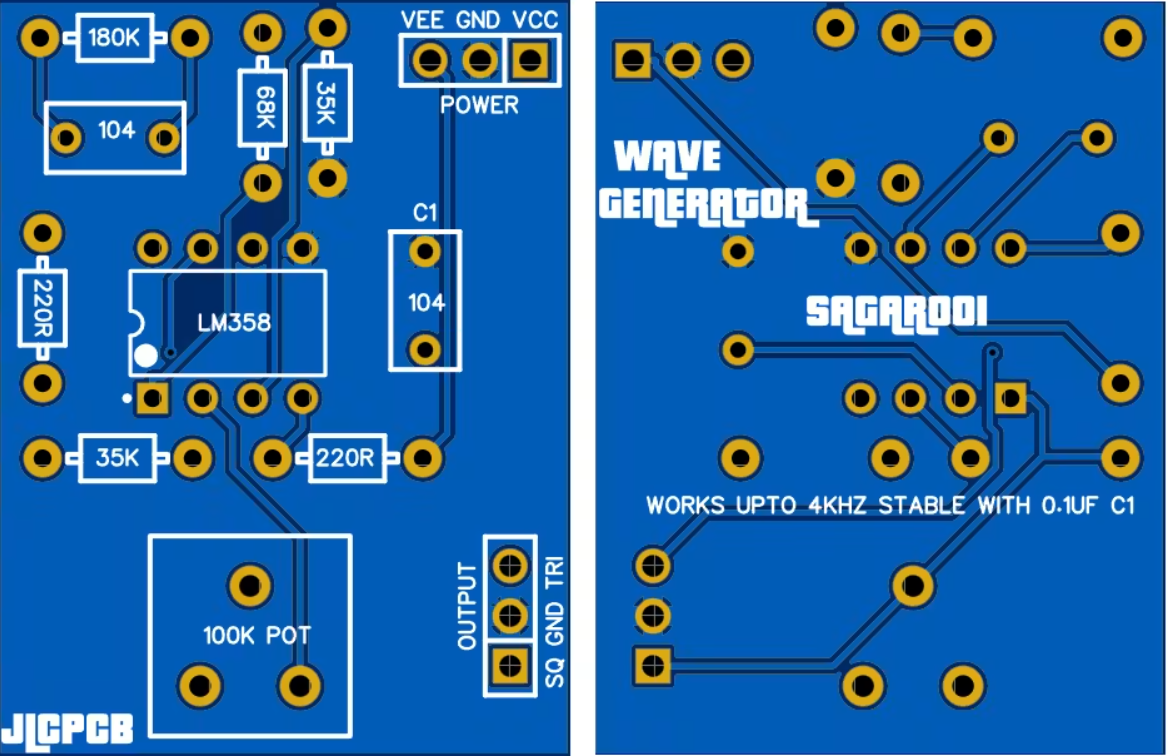
PCB prototype — both outputs tested
Original Hackster article: https://www.hackster.io/sainisagar7294/li-ion-batteries-got-a-new-charging-module-d04a46
TP5100-based dual-cell Li-ion charging module
I am building a portable lab bench power supply that needs two Li-ion cells in series (8.4V total). The problem: standard TP4056 modules only handle a single 4.2V cell. I needed something that could charge both 4.2V single and 8.4V dual packs from a 12V adapter. That is where the TP5100 comes in a switching-mode charger with a single pin to select between 1S and 2S operation.
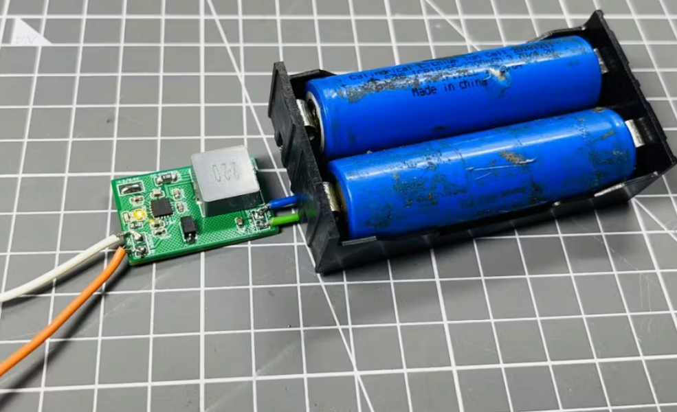
TP5100 Overview
The TP5100 is a step-down switching charger running at 400kHz. It accepts 5V–18V input and delivers up to 2A of programmable charging current via an external sense resistor. All protection is built in: input overcurrent, undervoltage, over-temperature, short circuit, and reverse battery.
Key specs:
• Input: 5V–18V (covers 12V adapters)
• Max charging current: 2A (programmable)
• Switching frequency: 400kHz
• Cell configuration: 1S (4.2V) or 2S (8.4V) via onboard solder pad
Charging Phases
The IC steps through three phases automatically:
- Trickle: if the battery is over-discharged below 2.8V, charges at 1/10th of max current until it recovers.
- Constant current: charges at the set max current until voltage nears the target.
- Constant voltage: holds at 4.2V (or 8.4V); current tapers to ~0.07C, then terminates.
Two onboard LEDs show live charge status.
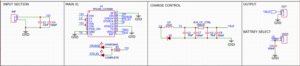
Circuit with 1S/2S selection and sense resistor
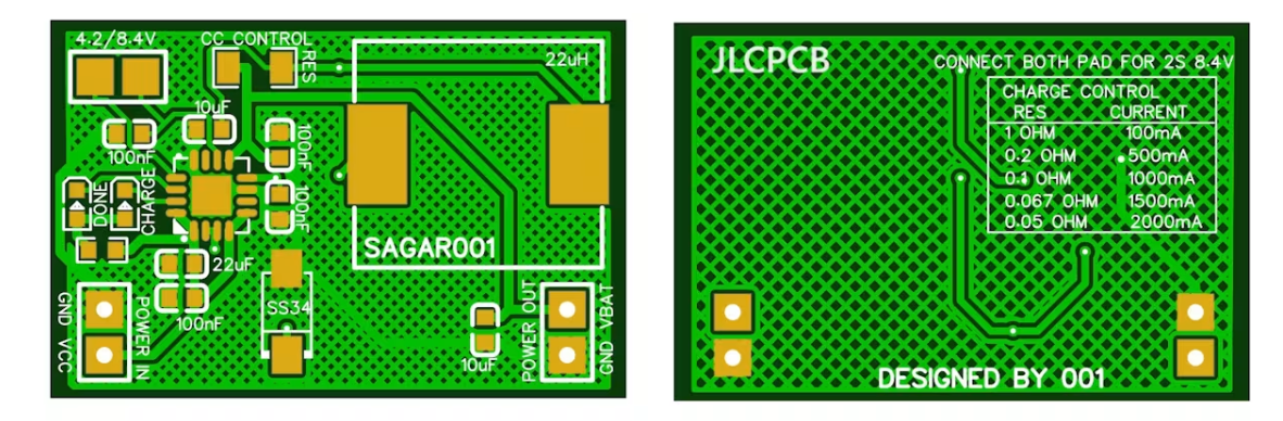
Compact PCB with separated input/output sections
Testing
Important: this module does not support balance charging. For 2S packs, use identical cells from the same batch and manufacturer so initial capacities are matched.
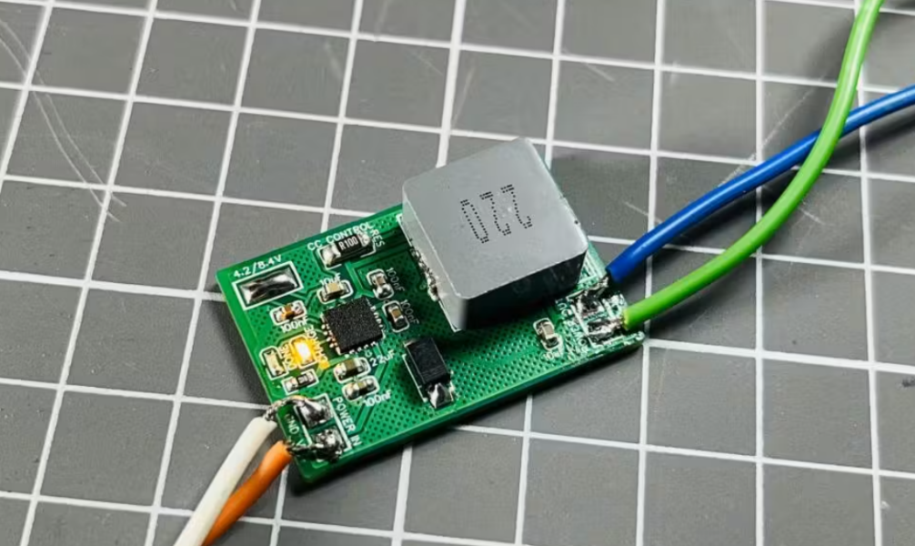
Results 1S cell pre-charged at 4.1V: ~300mA (CV taper phase). 2S pack: ~500mA. Both are expected since cells were near full. All protection features tested and working.
Original Hackster article: https://www.hackster.io/sainisagar7294/fast-charging-module-for-lithium-batteries-a1eaae
IP2312-based 3A fast-charging module
The TP4056 is one of the most popular Li-ion charging modules. It is cheap, widely available, and paired with a built-in protection IC. But it uses a linear voltage regulator internally, which means significant heat at higher currents and a practical ceiling of around 450mA before the module gets too hot to handle. I built a custom board around the IP2312, a buck-based charging IC that delivers up to 3A at 94% efficiency.
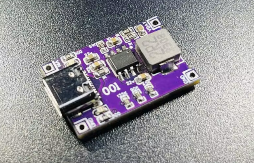
Why IP2312?
Unlike the TP4056, the IP2312 uses a built-in buck converter running at 750kHz which means far less heat, far better efficiency. All protection features (overvoltage, undervoltage, over-temperature, trickle charging, short circuit) are packed into the IC itself, so no separate protection chip is needed.
Key specs:
• Input: 4.5–5.5V via USB-C or solder pads
• Max charging current: 3A (set via external resistor)
• Default nominal current: 2.1A
• Efficiency: 94% at 3.7V/2A
• Trickle charge current: 100mA
• Standby current: 40µA
• Overvoltage cutoff: Vin > 5.6V
• Battery voltage support: 4.20V / 4.30V / 4.35V / 4.40V
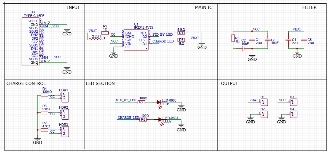
Schematic — buck converter section and filter stage
PCB Design
I kept the same form factor as the TP4056 board for a drop-in upgrade. Charging current is set by solder pads on the PCB back — left floating, it defaults to 2.1A. The layout follows input-to-output flow to isolate switching transients. The NTC pin is pulled down with a 51kΩ resistor as I am using this as a breakout board. Two status LEDs monitor charging.
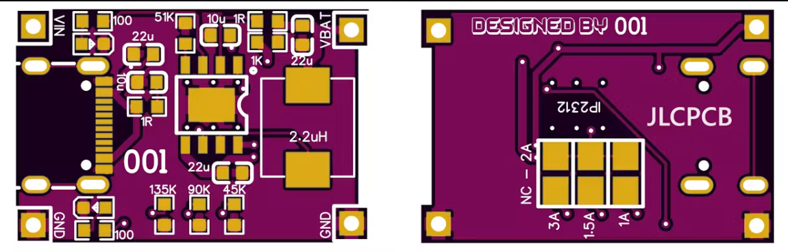
PCB — same footprint as TP4056, USB-C input
Testing
I powered up with a 100mA current-limited supply first worked first try. Then charged a 3.9V Li-ion at default settings. Comparison with the same 4.0V battery:
• TP4056: 450mA
• IP2312: ~1A
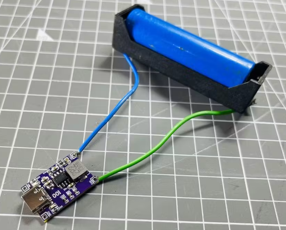
More than double the charging rate. Heat was minimal at full load, confirming the 94% efficiency claim. All protection features tested normal.