ESP OTA Updates: Ship Once, Update Forever

The day you ship a product without OTA updates is the day you commit to never fixing bugs or adding features without physically retrieving every device. That's fine for a breadboard. It's a business problem at any scale. Here's how OTA works on ESP, from the simplest version to what production systems need.

How OTA Works Under the Hood

The ESP's flash is divided into partitions defined by a CSV file. For OTA, you need at least two app partitions: ota_0 and ota_1. Your current running firmware resides in one of them. During an OTA update, the new firmware writes to the other, the inactive one. When writing is complete and the SHA256 hash verifies, the bootloader checks it on reboot, and the device restarts into the new firmware.**

If the new firmware fails to boot correctly, for example if it crashes repeatedly or never calls esp_ota_mark_app_valid_cancel_rollback(), the bootloader automatically marks the update as invalid and reverts to the previous working firmware on the next power cycle. This rollback mechanism prevents bricks and is a critical production safety net.

Three OTA Methods, Pick Your Level

ArduinoOTA, for development

Install the library, add four lines to setup(), and your board appears in the Arduino IDE port list over the network. Upload new firmware exactly like USB over Wi-Fi. No authentication by default, so add a password at minimum. Not for production, but for rapid development iteration it is extremely convenient.

HTTP OTA, the production standard

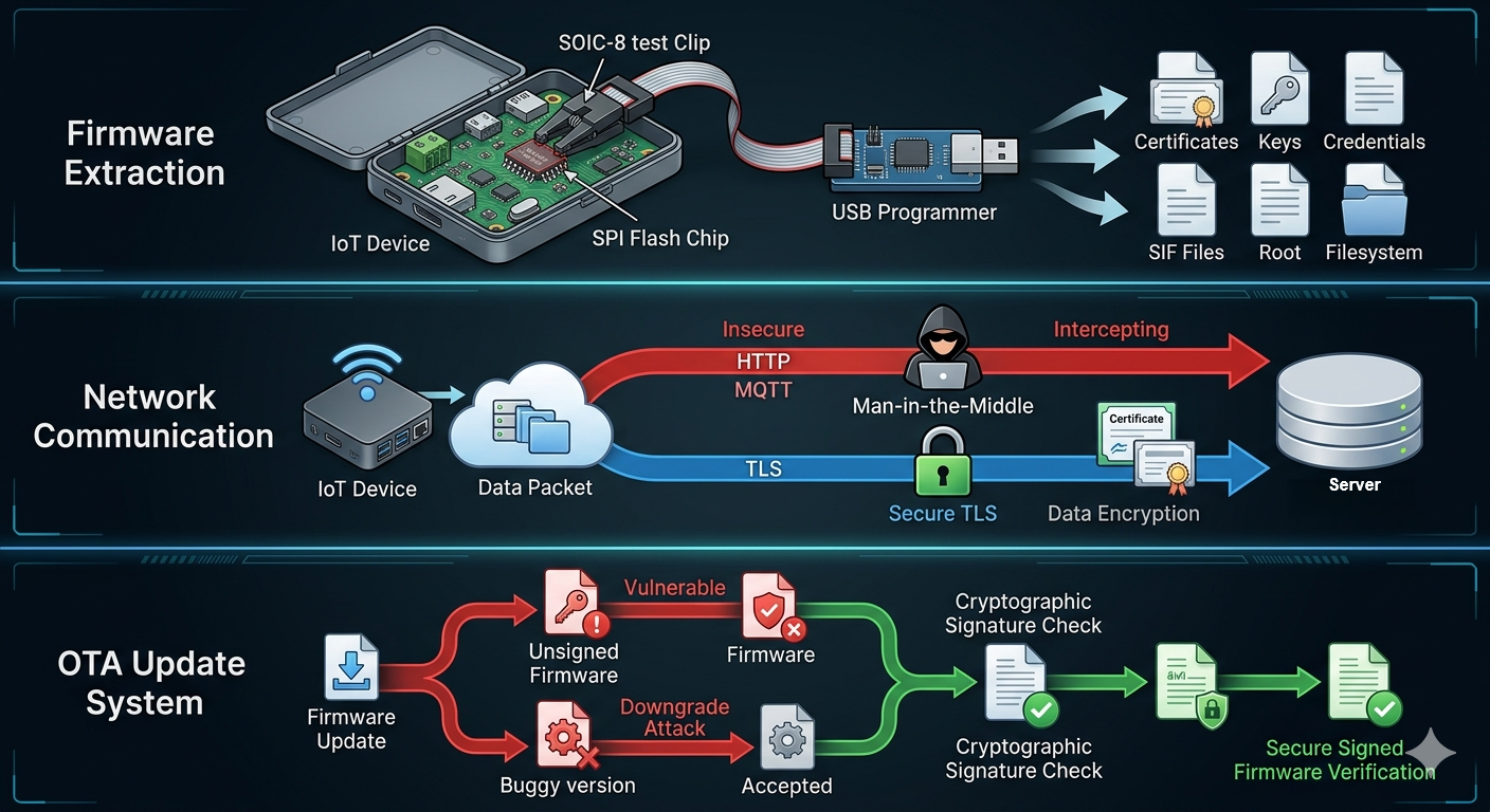
Your device polls an HTTPS endpoint every N hours, or on command from the server. The endpoint returns either a 304 Not Modified response, meaning nothing to update, or a new firmware binary. The device downloads it to the inactive partition, verifies integrity, optionally checks signature, then reboots. ESP-IDF's esp_https_ota() handles most of this in a few lines of code.

Wireless & IOT
ESP Sleep Modes: Light Sleep and Choosing the Right Mode

ESP Sleep Modes: The Practical Guide to Not Killing Your Battery

In the previous post, we covered the five power states of the ESP32 family and took a deep dive into deep sleep, the go-to mode for battery-powered sensor nodes. Now we turn to light sleep, a mode that offers sub-milliampere current consumption while preserving RAM state and enabling fast wake-up.

Light Sleep: The Overlooked Middle Ground

Light sleep pauses the CPU while keeping RAM powered, typically around ~0.8 mA depending on configuration. When a wake source fires, execution resumes exactly where it stopped, no reboot, no re-initialization required. If your device needs to respond quickly to GPIO events but does not need to stay fully active all the time, light sleep is often the right choice.

The tradeoff is power. While ~0.8 mA is significantly lower than active mode, it is still much higher than deep sleep (~10 µA). At scale, this difference has a major impact on battery lifetime.

For devices that wake frequently, light sleep can be more energy-efficient overall because it avoids the repeated cost of system reboots and Wi-Fi reconnections. However, for longer sleep intervals measured in minutes or hours, deep sleep remains the clear winner.

Wake sources for light sleep include timers, GPIO interrupts, UART activity, and capacitive touch sensors. These are configured similarly to deep sleep using APIs such as esp_sleep_enable_timer_wakeup() and esp_sleep_enable_gpio_wakeup().

Wireless & IOT
Deep Sleep: The Right Tool for Battery Sensors

For a device that wakes up periodically to send data and then sleeps, which covers most of the battery IoT nodes, deep sleep is what you want. You call esp_deep_sleep_start() and the chip powers down to approximately 10 µA, keeping only the RTC oscillator ticking. Your specified wakeup source brings the chip back.

The GPIO16 trick for ESP8266: On the original ESP8266, you must wire GPIO16 to RST to wake from deep sleep via timer. The RTC fires a low pulse on GPIO16 which resets the chip. Forget this wire and your device sleeps forever.

On the ESP32, the timer wakeup is cleaner, no external wire needed. Call esp_sleep_enable_timer_wakeup(duration_in_microseconds) before esp_deep_sleep_start() and you're done.

Surviving Deep Sleep: RTC Memory

 Here's the subtle part: deep sleep kills your chip's state. All RAM is wiped. Your variables are gone. To preserve data across sleep cycles, use RTC memory, a small (16 KB) memory region powered by the RTC that survives deep sleep.

In Arduino: RTC_DATA_ATTR int bootCount = 0; that RTC_DATA_ATTR prefix stores the variable in RTC SLOW memory. Use it for boot counters, cached Wi-Fi credentials, last sensor value, or anything you need to remember between wakes.

 Cache your Wi-Fi BSSID and channel in RTC\_DATA\_ATTR variables. On subsequent wakes, pass them to WiFi.begin() explicitly to skip the channel scan. This alone cuts reconnect time from 3–5 seconds to under 1 second, a significant battery saving at scale.
Wireless & IOT
Relay vs Solid State Relay (SSR): Which One to Use in Automation Systems?

Relays are widely used in automation systems to control electrical loads such as motors, lamps, and industrial equipment. Two common types are mechanical relays and solid state relays (SSR). While both serve the same purpose, their working principles and performance characteristics are significantly different.

This article compares both relay types to help engineers choose the right solution for their application.

Working Principle

Mechanical Relay

A mechanical relay uses an electromagnetic coil to physically switch contacts.

Key characteristics:

  • Uses moving parts
  • Provides electrical isolation
  • Produces clicking sound during operation

Solid State Relay (SSR)

An SSR uses semiconductor components (triac, MOSFET, or optocoupler) to switch loads without moving parts.

Key characteristics:

  • No mechanical movement
  • Silent operation
  • Faster switching

image.png

Performance Comparison

Feature Mechanical Relay SSR
Switching Speed Slow (ms) Fast (µs)
Lifespan Limited (wear) Very long
Noise Audible click Silent
Heat Generation Low Higher
Power Consumption Coil required Low control power
Isolation High High (optical)

Load Handling

Mechanical Relay

  • Suitable for AC and DC loads
  • Handles high current surge
  • Better for inductive loads

SSR

  • Ideal for frequent switching
  • Best for resistive loads
  • Some types limited to AC only (triac-based)

image.png

Advantages and Limitations

Mechanical Relay Advantages

  • Low cost
  • Handles high current
  • Good isolation

Mechanical Relay Limitations

  • Contact wear over time
  • Slower switching
  • Mechanical noise

SSR Advantages

  • Long lifespan
  • Fast switching
  • No mechanical noise

SSR Limitations

  • Heat dissipation required
  • Higher cost
  • Leakage current (important for low-load systems)

Engineering Considerations

Choose based on application:

  • Use mechanical relay for:
    • Motor control
    • High current switching
    • Low-frequency operation
  • Use SSR for:
    • High-speed switching
    • Silent operation
    • Long-term reliability

Thermal management is critical when using SSR, especially in high-current applications.

Both mechanical relays and SSRs are essential components in automation systems. Mechanical relays are robust and cost-effective for general-purpose switching, while SSRs provide faster, quieter, and more reliable operation for high-frequency switching applications.

Selecting the right relay depends on load type, switching frequency, and system requirements.

#Automation#
#Relay#
#SSR#
#EmbeddedSystem#
#PowerElectronics#
#ControlSystem#

Automation & Control
Measuring Motorcycle Speed Using Hall Effect Sensor and Interrupt-Based Pulse Counting

Accurate speed measurement is essential in vehicle monitoring and safety systems. In this project, motorcycle speed is measured using a Hall Effect sensor combined with interrupt-based pulse counting on a microcontroller.

A magnet attached to the wheel generates pulses as the wheel rotates. These pulses are detected by the sensor and converted into speed using wheel dimension parameters.

System Overview

The system uses a Hall Effect sensor mounted near the rotating wheel. Each time the magnet passes the sensor, a pulse is generated.

image.png

Hardware Architecture

Main components:

  • Hall Effect sensor (NJK-5002C)
  • ESP32 microcontroller
  • LCD display
  • Power supply (battery + step-down)
  • Additional sensors (distance monitoring system)

The wiring configuration is shown in the system diagram.

image.png

Interrupt-Based Pulse Detection

To ensure accurate measurement, pulse detection is handled using interrupts.

Each pulse corresponds to one wheel rotation (or fraction, depending on magnet count).

Basic logic:

  1. Sensor detects magnet → generates pulse
  2. Interrupt triggers on rising/falling edge
  3. Pulse counter increments
  4. Speed calculated over time interval

This approach ensures no pulses are missed, even at high speeds.

Speed Calculation Method

Speed is calculated using wheel circumference.

From the configuration procedure:

  • Tire width
  • Tire height
  • Wheel diameter

These parameters are used to calculate effective wheel circumference.

Formula:

image.png

Where:

image.png

Final output is converted to km/h.

System Calibration

Accurate speed depends on proper calibration.

Key parameters:

  • Tire width and aspect ratio
  • Wheel diameter
  • Unit system (metric or imperial)

Incorrect values will result in inaccurate speed readings.

Integration with Safety System

This speed measurement is integrated into a safe distance warning system.

Based on system logic:

  • Speed affects warning level
  • Distance sensors monitor front and rear
  • System outputs:
    • SAFE
    • WARNING
    • DANGER

image.png


Engineering Considerations

Important design factors:

  • Sensor alignment affects detection accuracy
  • Noise filtering may be required
  • Debouncing needed for stable pulse detection
  • Interrupt handling must be efficient

Using interrupt-based detection significantly improves reliability compared to polling methods.

Conclusion

The implementation demonstrates how Hall Effect sensors and interrupt-based pulse counting can be used for accurate real-time speed measurement in vehicles.

By combining mechanical calibration, embedded processing, and system integration, the design provides a reliable foundation for advanced automotive monitoring systems.

#TestAndMeasurement#
#HallEffectSensor#
#RPMMeasurement#
#EmbeddedSystem#
#ESP32#
#Automation#

Test & Measurement
How to Measure AC Current Using CT Sensors: A Practical Guide

Current Transformer (CT) sensors are widely used for measuring AC current in industrial and embedded systems. They provide electrical isolation and allow high current measurement without direct electrical contact with the conductor.

This guide explains how to properly use CT sensors with microcontrollers for accurate current measurement.

How CT Sensors Work

A CT sensor operates based on electromagnetic induction. When AC current flows through the primary conductor, it induces a proportional current in the secondary coil.

Key points:

  • Output is current (not voltage)
  • Requires burden resistor to convert to voltage
  • Only works with AC signals

image.png

Basic Connection to Microcontroller

A CT sensor cannot be connected directly to an ADC input. The output must be conditioned.

Required components:

  • Burden resistor
  • RC low-pass filter (optional)
  • Voltage divider / biasing (for ADC protection)

Basic flow:

CT Sensor → Burden Resistor → Filter → ADC Input

image.png

Burden Resistor Selection

The burden resistor converts CT output current into measurable voltage.

Formula:

image.png

Where:

image.png

Selection considerations:

  • Output voltage must stay within ADC range (0–3.3V / 5V)
  • Too large → saturation
  • Too small → low resolution

Proper selection is critical for measurement accuracy.

Signal Conditioning and Offset

Because CT output is AC (positive & negative), ADC input must be adjusted.

Common approach:

  • Add DC offset (bias) to shift signal into positive range
  • Use capacitor filtering to stabilize waveform

This ensures safe and stable ADC readings.

image.png

RMS Calculation Implementation

After signal acquisition:

  1. Sample ADC values continuously
  2. Convert to voltage/current
  3. Apply RMS calculation
  4. Display or log results

To improve accuracy:

  • Use multiple sampling cycles
  • Apply filtering
  • Calibrate scaling factor

Common Mistakes

Avoid these common issues:

  • ❌ No burden resistor (dangerous for CT)
  • ❌ Direct connection to ADC
  • ❌ Incorrect resistor value
  • ❌ Ignoring signal offset
  • ❌ Low sampling rate

These mistakes can cause inaccurate readings or hardware damage.

Practical Applications

CT sensors are commonly used in:

  • Energy monitoring systems
  • Industrial load measurement
  • Smart meters
  • Motor current monitoring
  • Data logging systems

Conclusion

CT sensors provide a safe and effective method for measuring AC current in embedded systems. With proper signal conditioning, correct burden resistor selection, and accurate RMS calculation, reliable current measurement can be achieved for both industrial and IoT applications.

#Sensors#
#CTSensor#
#CurrentMeasurement#
#EmbeddedSystem#
#AnalogSignal#
#TestAndMeasurement#

Test & Measurement
CT Sensor vs Hall Effect Sensor for Current Measurement: Which One to Choose?

Current measurement is a fundamental requirement in many embedded and industrial systems. Two commonly used technologies are Current Transformer (CT) sensors and Hall Effect sensors. Each has distinct characteristics, advantages, and limitations depending on the application.

This article compares both sensor types to help engineers select the most suitable solution.

Working Principle

CT Sensor (Current Transformer)

CT sensors operate based on electromagnetic induction. When AC current flows through the primary conductor, it induces a proportional current in the secondary winding.

Key characteristics:

  • Only works with AC signals
  • Provides isolated measurement
  • Requires burden resistor for voltage conversion

Hall Effect Sensor

Hall Effect sensors measure magnetic fields generated by current flow. The sensor outputs a voltage proportional to the magnetic field strength.

Key characteristics:

  • Works with both AC and DC
  • Provides direct voltage output
  • Typically integrated with signal conditioning

image.png

Measurement Capability

Feature CT Sensor Hall Effect Sensor
AC Measurement ✅Yes ✅Yes
DC Measurement ❌No ✅Yes
Isolation ✅High ✅Moderate
Accuracy High (AC) Moderate–High
Cost Low Medium

Signal Conditioning

CT sensors require additional circuitry:

  • Burden resistor
  • Filtering (RC)
  • Voltage scaling

Hall sensors typically provide:

  • Analog voltage output
  • Built-in amplification
  • Minimal external components

image.png

Application Comparison

CT Sensor is suitable for:

  • Industrial AC monitoring
  • Energy metering systems
  • High-current applications
  • Electrical panel measurement

Hall Effect Sensor is suitable for:

  • Battery monitoring systems
  • DC motor control
  • Automotive applications
  • Bidirectional current sensing

image.png

Accuracy and Noise Consideration

  • CT sensors provide stable readings for sinusoidal AC signals
  • Hall sensors may introduce offset drift and noise
  • CT sensors require calibration for burden resistor scaling
  • Hall sensors require offset compensation for zero-current detection

Engineering Insight

Choosing the right sensor depends on system requirements:

  • Use CT sensor for high-current AC measurement with isolation
  • Use Hall Effect sensor for DC or bidirectional current measurement

For mixed systems (AC + DC), Hall Effect sensors are more flexible but come with higher cost and complexity.

Conclusion

Both CT and Hall Effect sensors are effective current measurement solutions, but their selection depends on the application. CT sensors are ideal for AC industrial monitoring, while Hall Effect sensors provide flexibility for both AC and DC systems.

Understanding these differences helps engineers design more accurate and efficient measurement systems.

#Sensors#
#CurrentMeasurement#
#CTSensor#
#HallEffect#
#EmbeddedSystem#
#AnalogSignal#

Test & Measurement
Understanding RMS Calculation in Microcontroller-Based Systems

Accurate measurement of AC signals is essential in many embedded systems, especially in power monitoring and industrial applications. Unlike DC signals, AC current and voltage vary continuously over time, making simple averaging ineffective. To represent the effective value of an AC signal, Root Mean Square (RMS) calculation is used.

This article explains how RMS is implemented in microcontroller-based systems and why it is critical for reliable measurement.

What is RMS?

RMS (Root Mean Square) represents the equivalent DC value of an AC signal that produces the same power.

Mathematically:

image.png

Where:

image.png

This calculation ensures that both positive and negative portions of the waveform contribute correctly to the final value.

image.png

Sampling Strategy in Microcontrollers

To compute RMS, the microcontroller must sample the signal at a sufficient rate.

Key considerations:

  • Sampling frequency should be at least 10× signal frequency
  • Use ADC with stable reference voltage
  • Ensure full waveform capture (multiple cycles preferred)

Typical steps:

  1. Read ADC value
  2. Convert to voltage/current
  3. Square the value
  4. Accumulate samples
  5. Compute mean
  6. Apply square root

image.png

Signal Conditioning Requirement

Raw AC signals cannot be directly connected to microcontroller ADC pins. Signal conditioning is required to:

  • Scale voltage within ADC range (0–3.3V / 5V)
  • Shift signal offset (if needed)
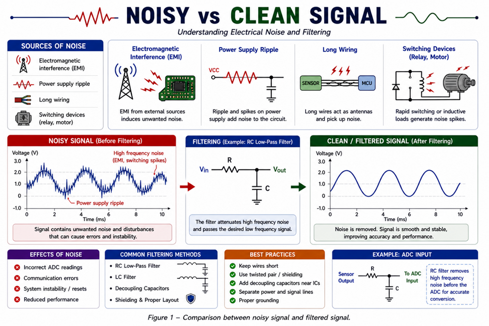
  • Filter noise using RC low-pass filter

For current measurement using CT sensors:

  • Burden resistor converts current to voltage
  • Filtering stabilizes waveform
  • Optional biasing shifts AC waveform into positive range

image.png

Improving Measurement Accuracy

Several techniques can improve RMS accuracy:

  • Use moving average filtering
  • Capture multiple waveform cycles
  • Implement zero-cross detection
  • Calibrate sensor scaling factors

Noise and insufficient sampling can significantly affect RMS results, especially in low-current measurements.

Practical Applications

RMS calculation is widely used in:

  • Energy monitoring systems
  • Industrial current data loggers
  • Smart meters
  • Motor load analysis
  • Power quality monitoring

Accurate RMS measurement enables better decision-making in both control and monitoring systems

RMS calculation is a fundamental technique for measuring AC signals in embedded systems. By combining proper sampling, signal conditioning, and efficient computation, microcontrollers can accurately represent real-world electrical parameters for industrial and IoT applications.

#TestAndMeasurement#
#RMSCalculation#
#EmbeddedSystem#
#SignalProcessing#
#Microcontroller#
#AnalogSignal#

Test & Measurement